Introduction
Today we were challenged to use the CNC Machines in the lab as well as mold and cast an object of our choosing. By the end of the lesson we were supposed to be familiar with molding and casting process as well as with many of the CNC Machines that we have available to us.
While we were learning how to mold and cast in lab, our class noticed that the Part A of the silicone rubber mixture was very viscous. We hypothesized that a greater ratio of Part B:Part A should be used to get a more workable and bubble-free mixture. I wanted to test this out in addition to cutting out various designs with the CNC Machines.
Components
This project required 4 components: the molding experiment, the drill bit cast, the gear cutout, and the beam cutout.
Part 1 - Molding Data
To test my classmates' theory, I prepared 6 mixtures of silicone rubber at varying concentrations (100:50, 100, 120, 130*, 140, and 200 by weight).
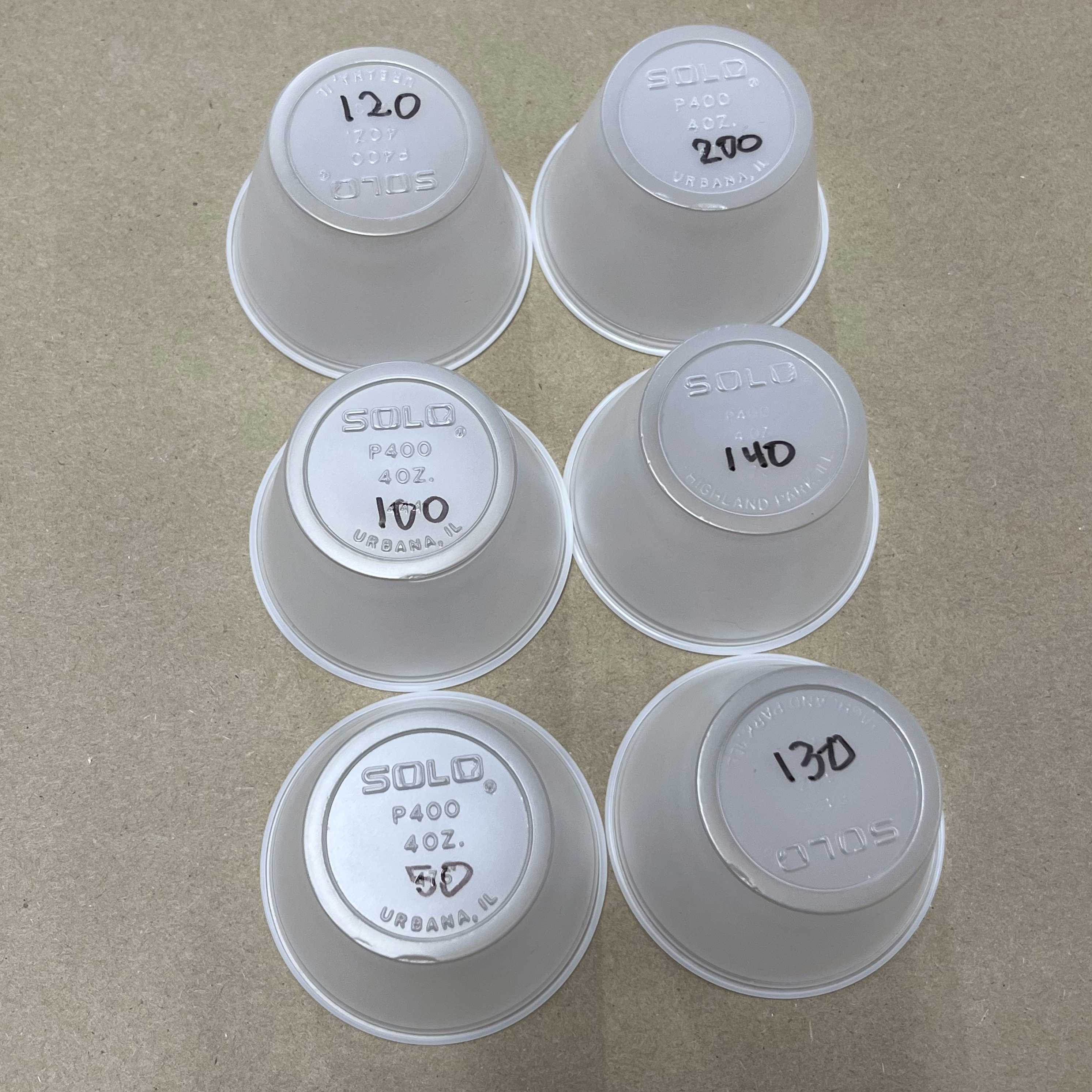
Fig 1. Cups labeled with ratios
*100:130 is the reccomended, control group.
I started by adding 25g of Part A and adjusted Part B accordingly.
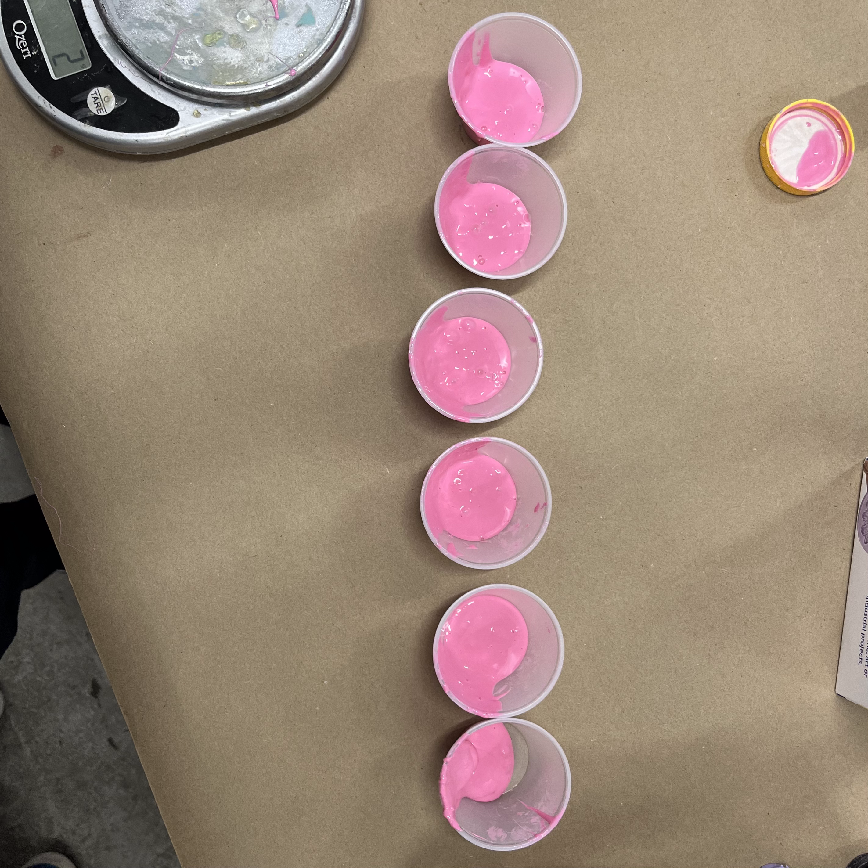
Fig 2. Cups filled with Part A
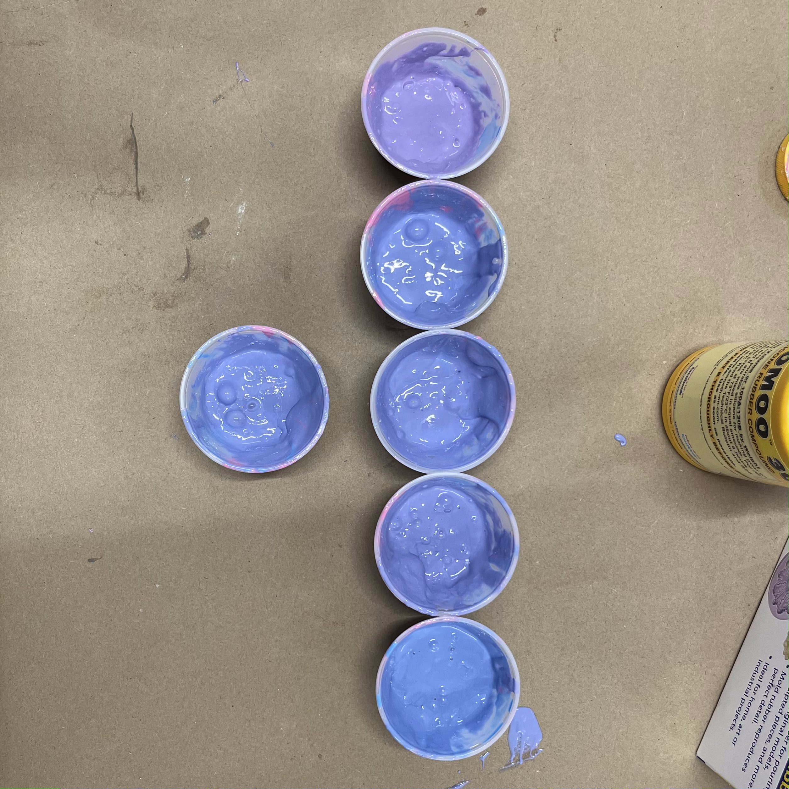
Fig 3. Cups filled with Part A mixed with Part B
After shaking the containers to remove bubbles, I let them cure, checking on them every 15 minutes. A sample was considered "cured" if a pencil could poke a hole through the silicone.
After all of the samples cured, I removed the plastic cup and trimmed away any excess.
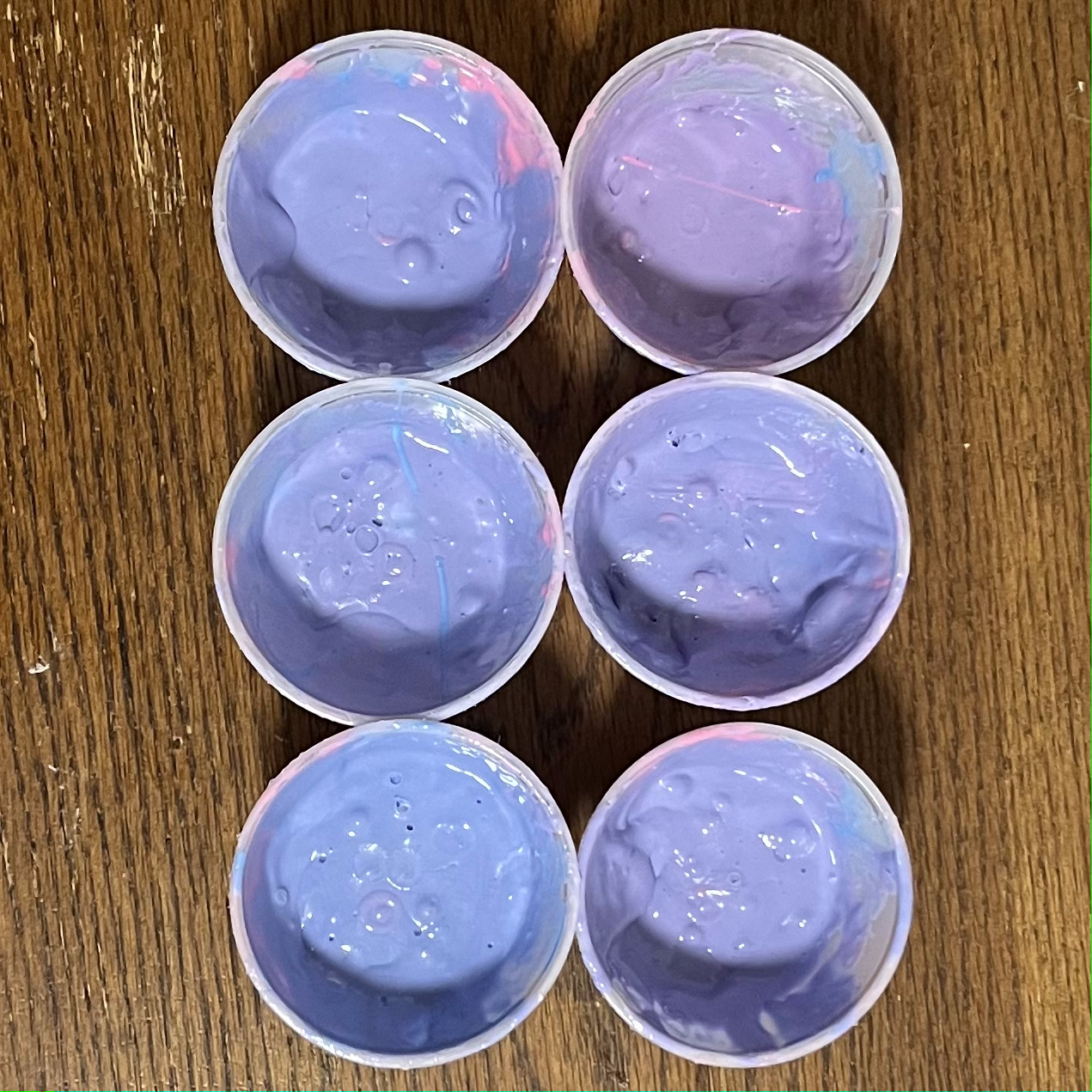
Fig 4. Cups immediately after setting
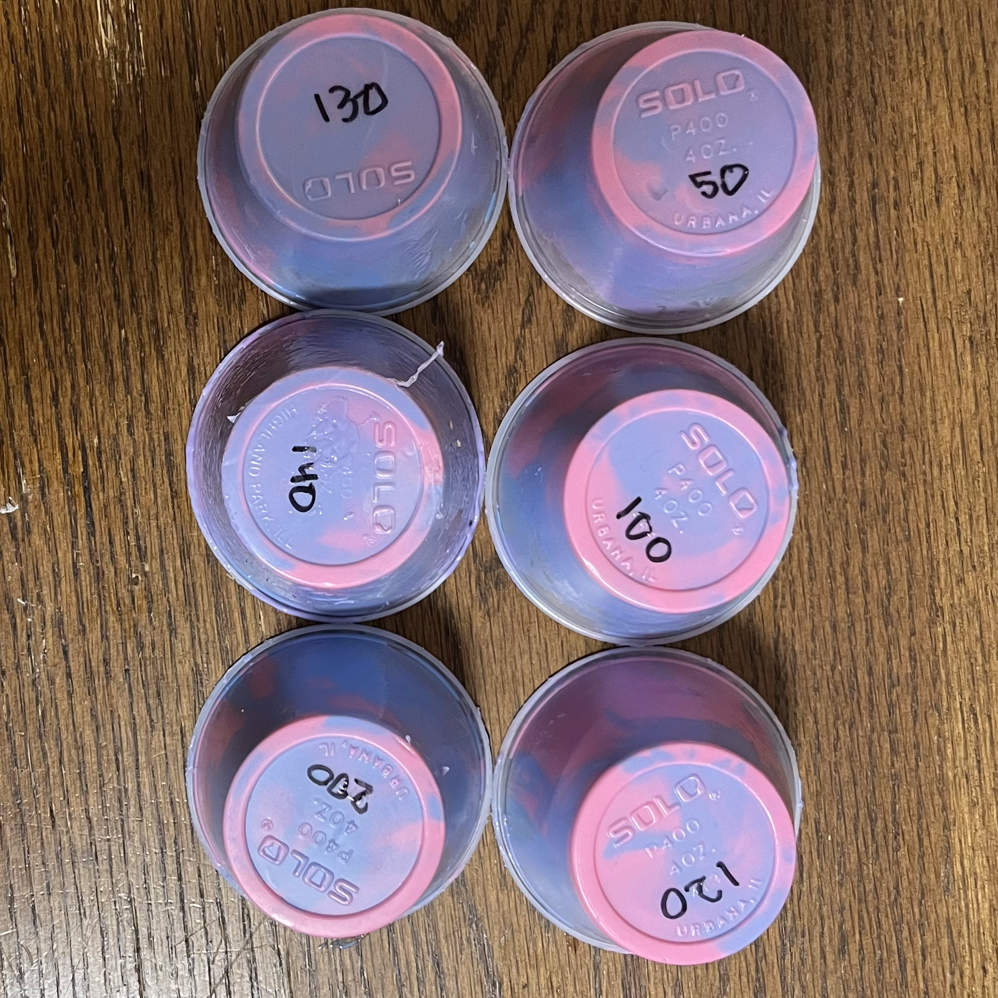
Fig 5. Ratios of set cups
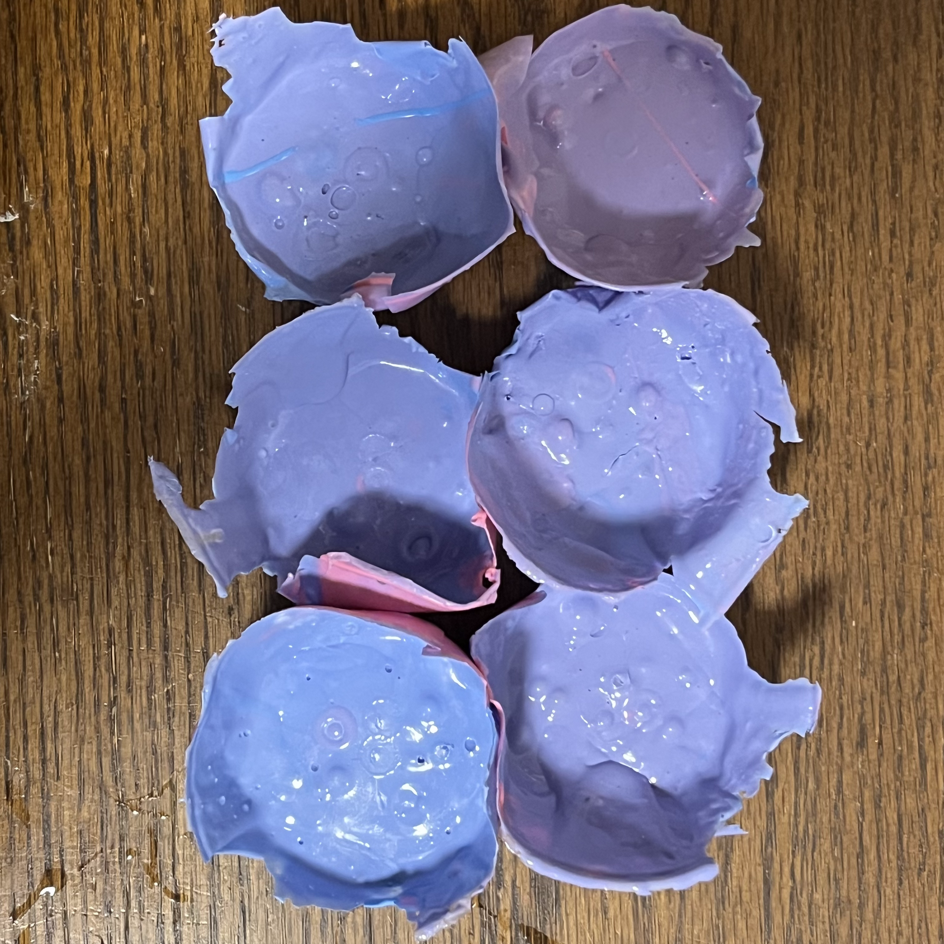
Fig 6. Molds with untrimmed material
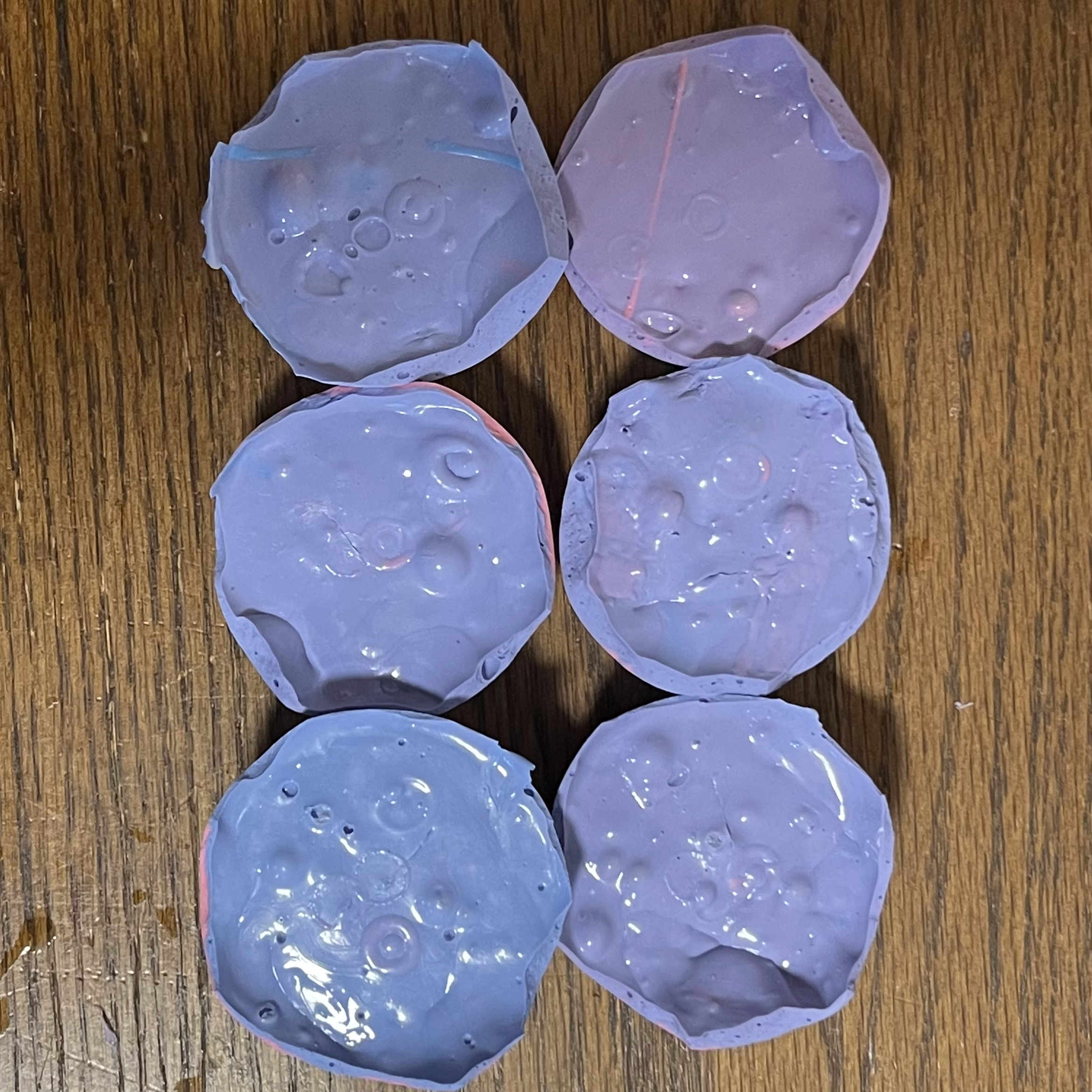
Fig 7. Trimmed molds
I then cut into each of the samples at the halfway point to see how much air was still trapped.
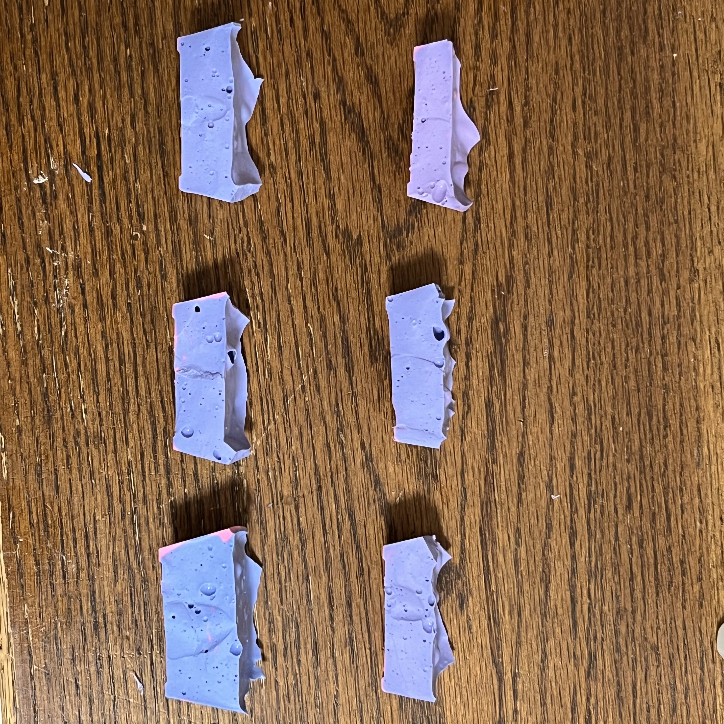
Fig 8. Cross-sections
I then recorded the last of the data and was shocked by what I had collected. My findings are displayed below.
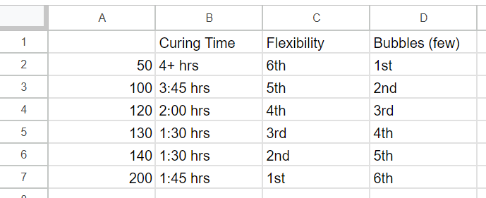
Fig 9. Data collected
As you can see from Figure 9, the 100:200 mixture trapped the most bubbles by far. This was not at all what our class, but was valuable nonetheless.
After anylizing all of the data, I decided to go with the 100:120 mix to minimize bubbles while still being workable (Part A was partially cured and required the fluidity of Part B).
Part 2 - Casting a Drill Bit
I started out by collecting a 1/8 inch drill bit and a wooden dowel. I placed these into a plastic cup such that the wooden dowel would provide a hole for air to escape.
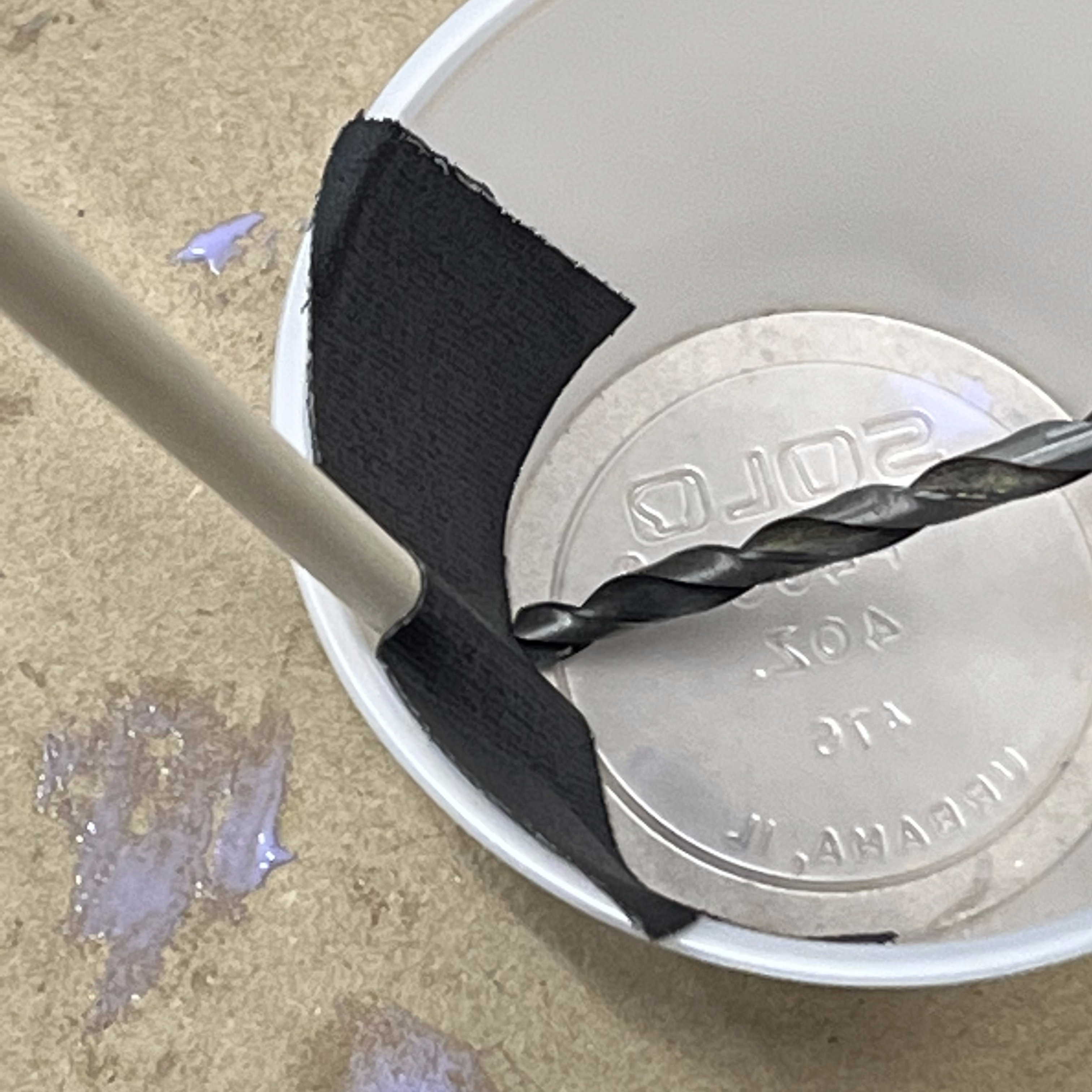
Fig 10. Cup with drill bit and dowel
Next, I mixed my 100:120 silicone mixture and added it to the cup.
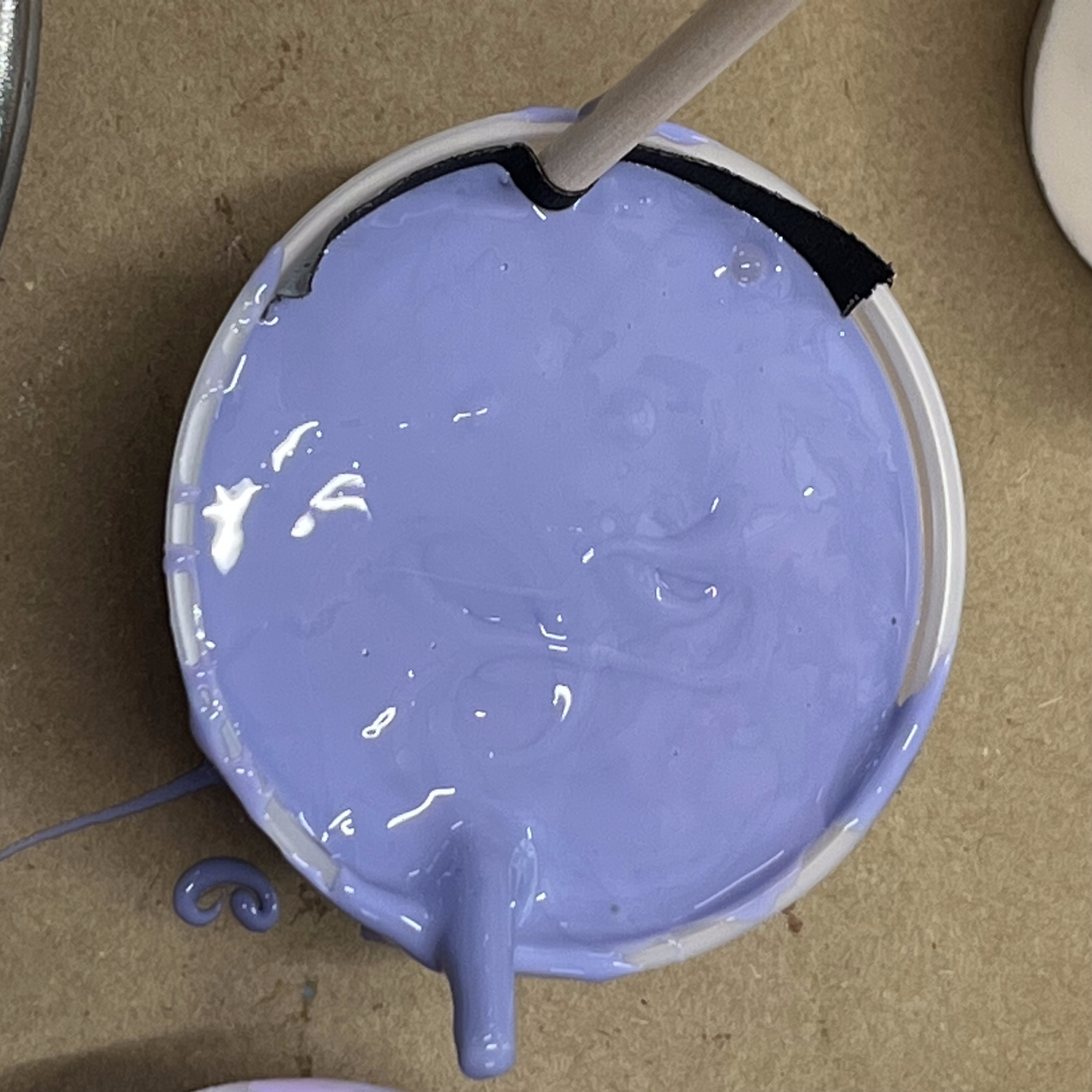
Fig 11. Cup filled with silicone
Because this was a larger volume I had to wait longer, so I checked in on my project the next day. I first used a utility knife to separate the plastic cup from the silicone.
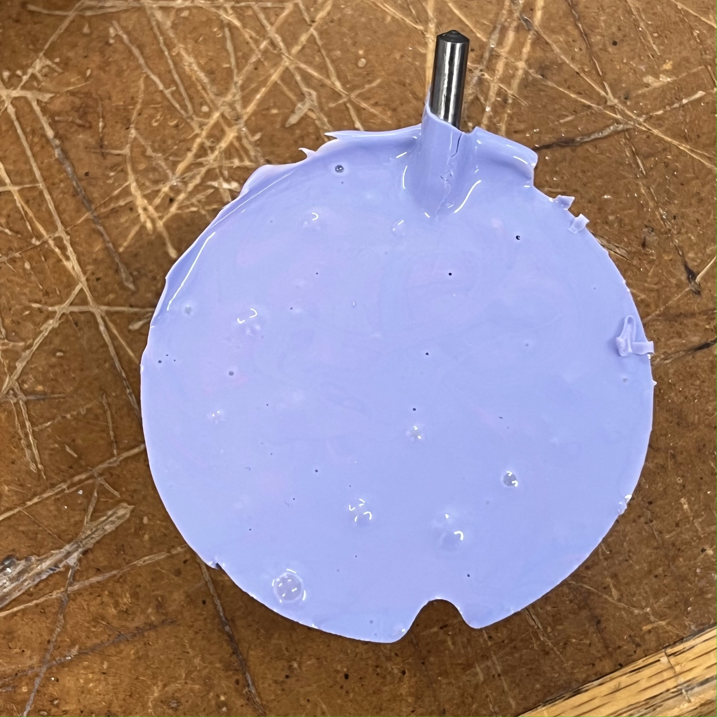
Fig 12. Mold removed from cup
I then used this guide to mix plaster and pour it into my mold. After about an hour and a half, I cut my mold open and removed my drill bit.
IMPORTANT: While opening my mold I pulled to hard and flung my drill bit onto the ground. It had already cured and remained mostly intact with only two major breakages.
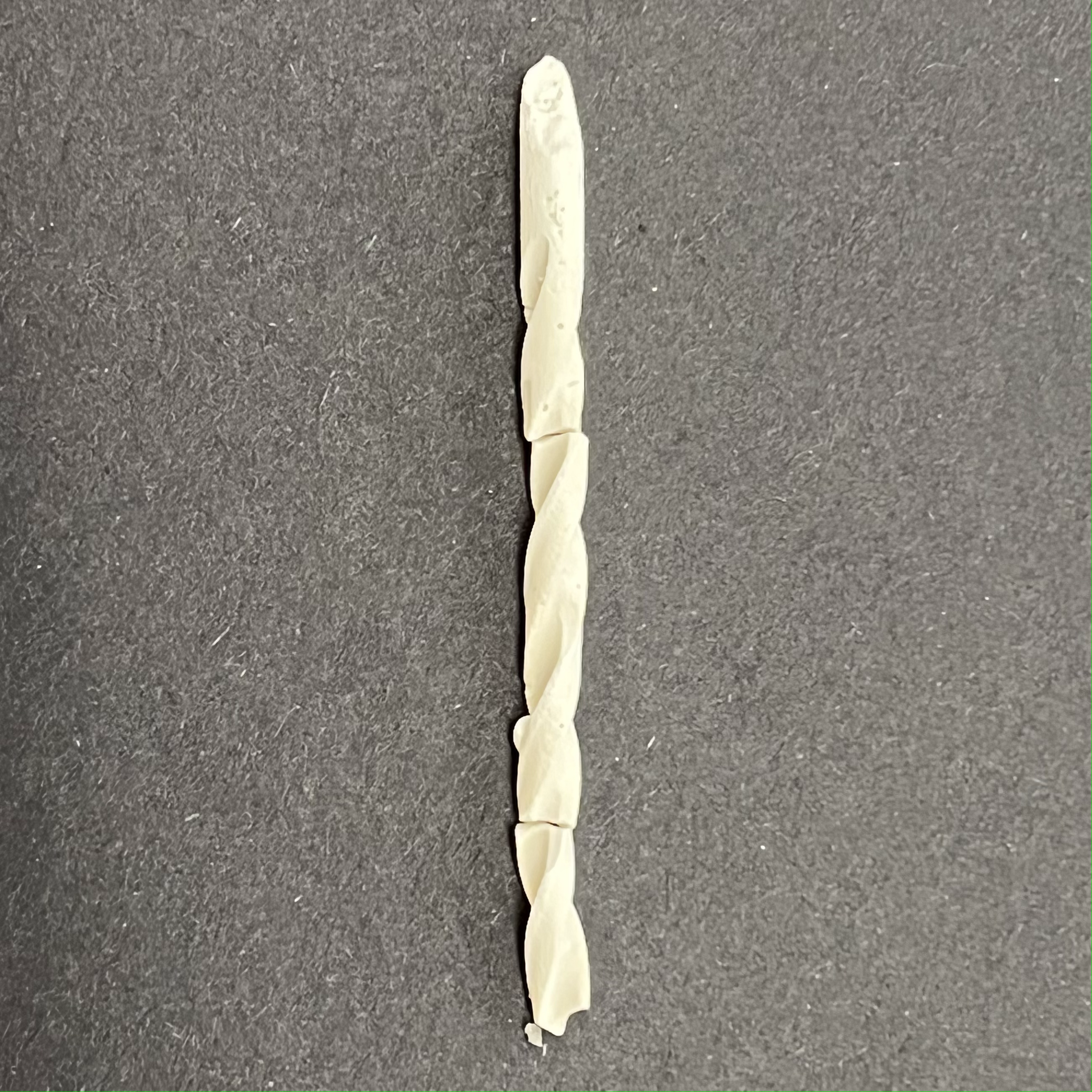
Fig 13. Casted drill bit
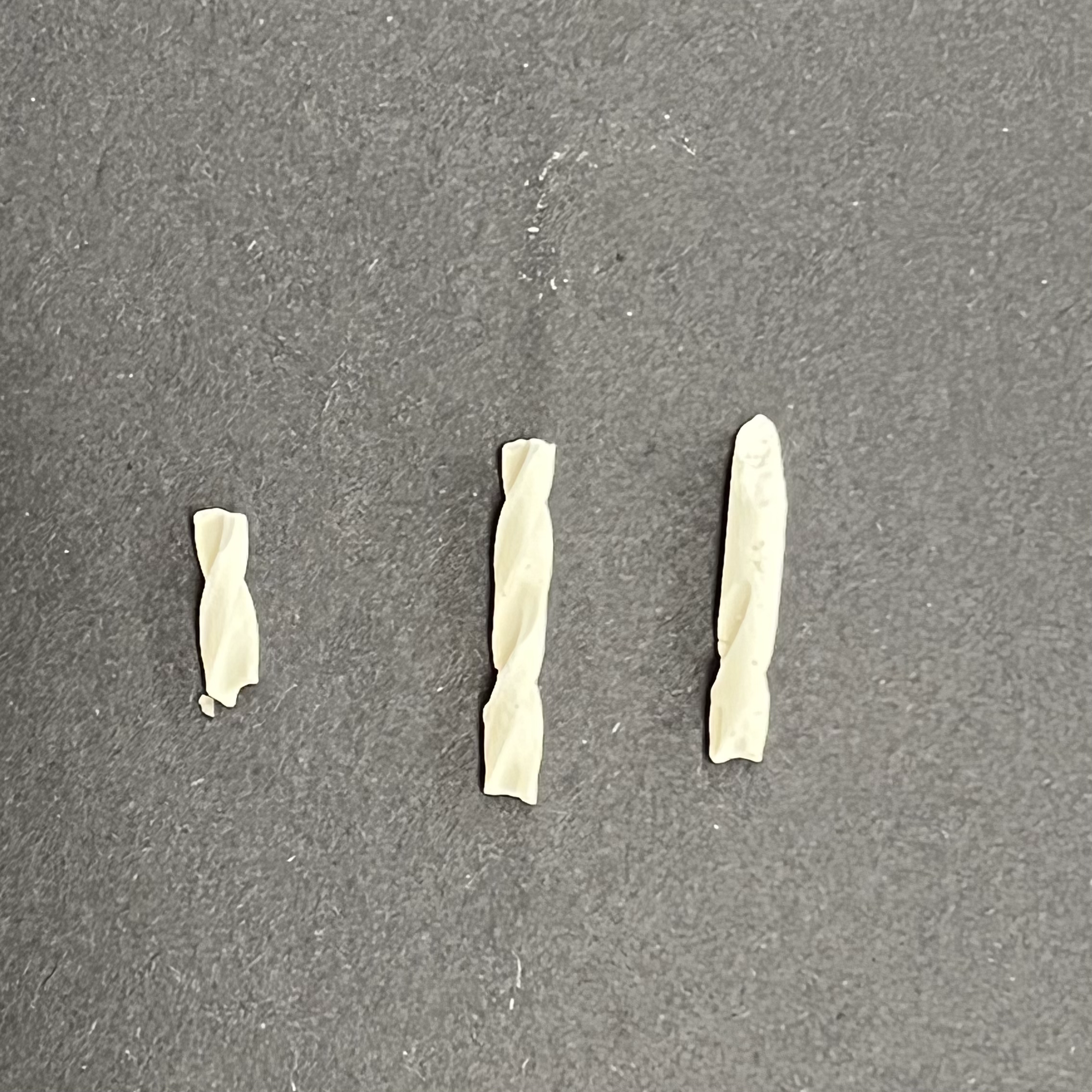
Fig 14. 3 pieces of cast
As you can see, there were still some air bubbles that I had not removed. If this was a convex or more durable cast, I would have used the belt sander to remove these protrusions, but due to its small and fragile nature, I let them remain. Below is the original bit for comparison.
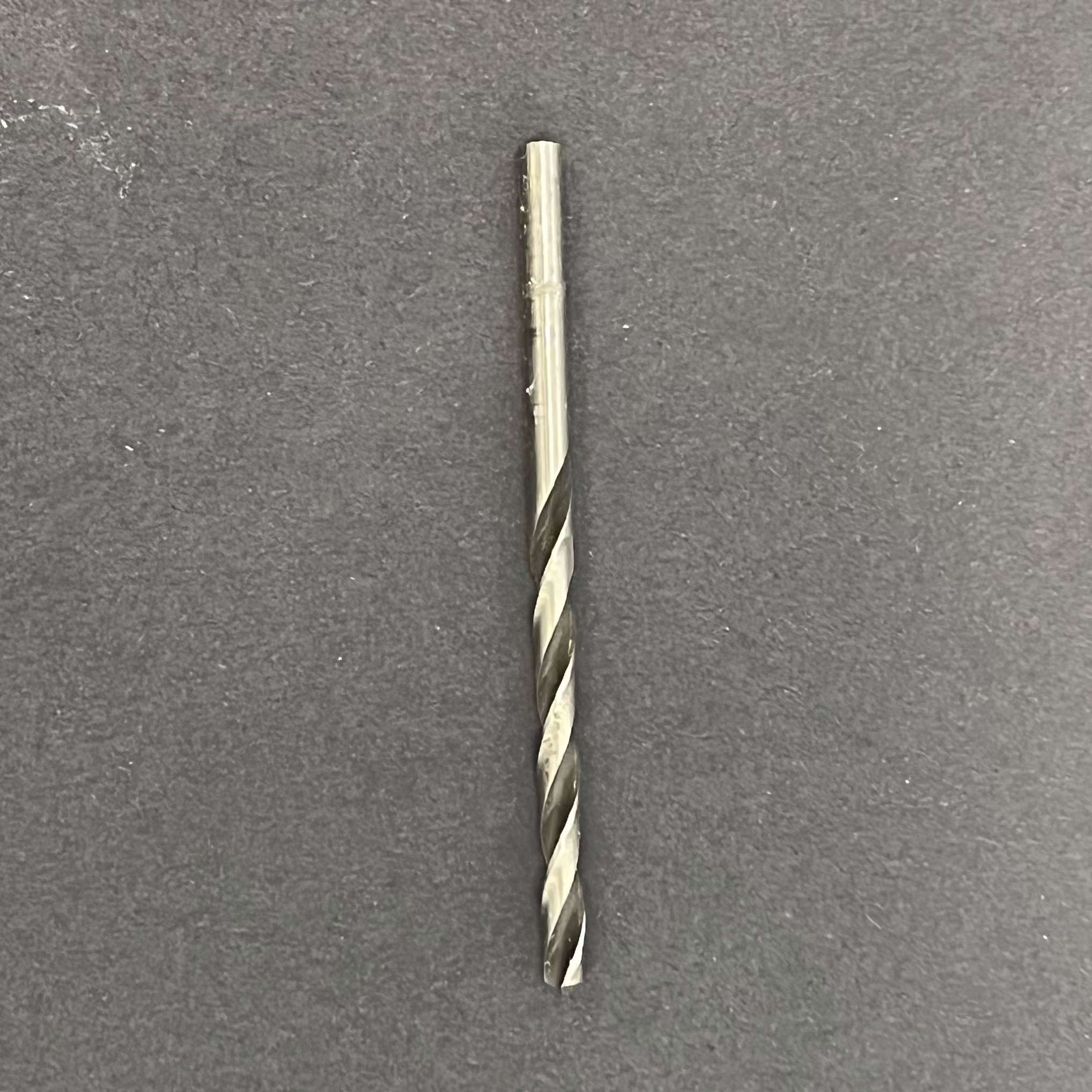
Fig 15. Original bit for comparison
Part 3 - Cutting OSB with the ShopBot
While thinking about what I wanted to do with the CNC Machines in the Lab, my mind wandered to an old assignment: Lesson 3 - Electronics and Tools. In this page, Professor Melenbrink talks about how gears are difficult to model but a useful exercise. I decided that the Lab's ShopBot would be a great way to cut out and test a set of gears of my own design.
Important: I generally try to skim over processes covered in previous documentations. However, due to the unique nature of this task, I will show all of my steps. See Documentation 3 for more information.
First, I created a sketch in Fusion360 and added a circle with a 50mm radius.
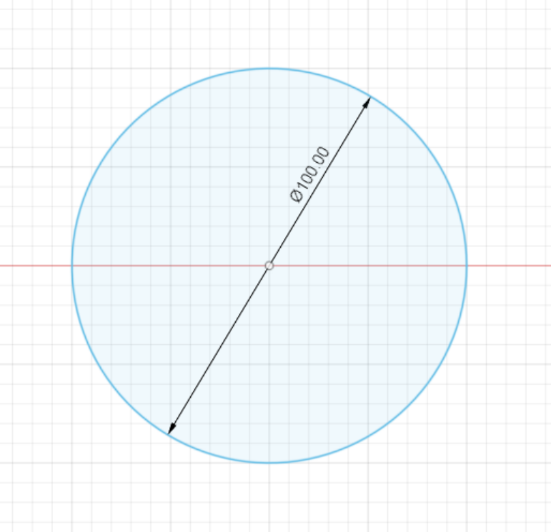
Fig 16. Circle sketch
Next, I decided what the width of each tooth should be (10mm) and created a rectangle with that dimension.
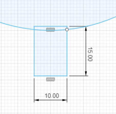
Fig 17. Measured rectangle
I then created a fit-point spline to create the rounded edge of the tooth. The exact dimensions of this spline will vary depending on the behavior you are looking for. I chose a wide curve to improve the chances of my gears working.
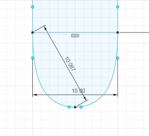
Fig 18. Fit-point spline addition
After this, I trimmed excess edges and created a circular pattern. I added copies of this tooth until the distance between the bases of the teeth was below 10mm (if this is the case, the gears can not mesh). With this process, I ended with 15 teeth.
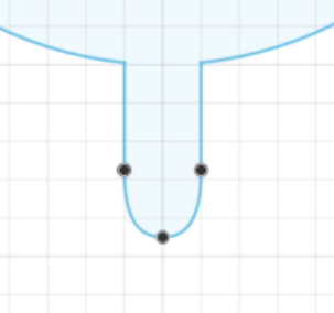
Fig 19. Trimmed tooth
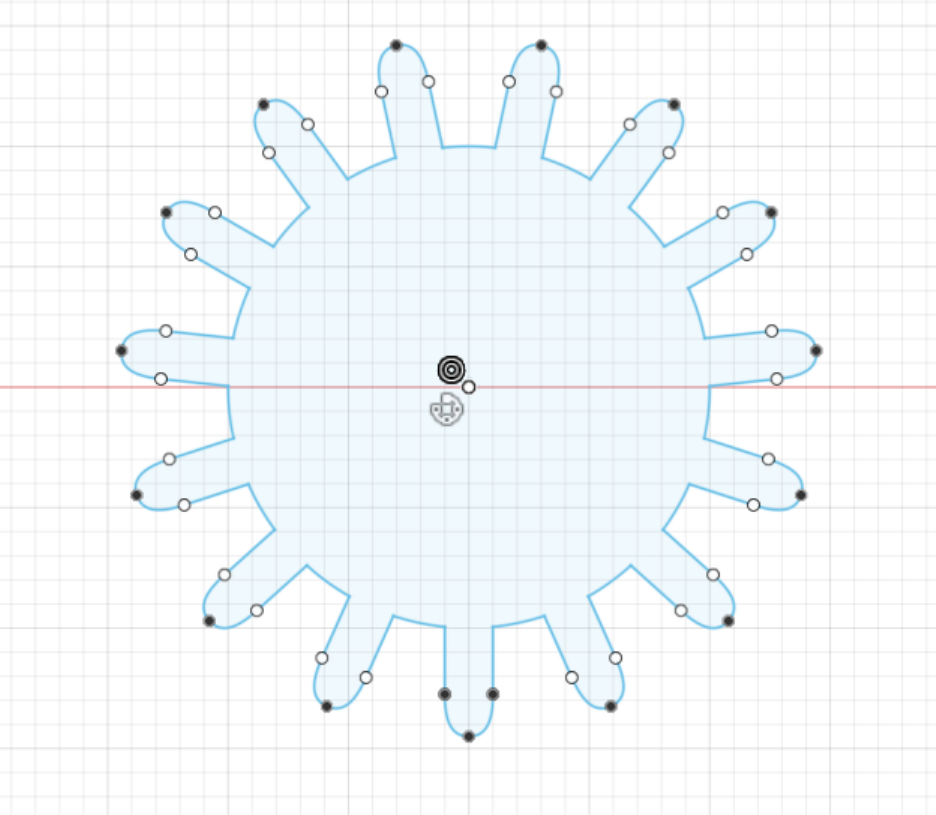
Fig 20. Circular pattern
Now that my final design was created, I exported it as a .dxf file (see "Files..." below) and opened it in Aspire.
Aspire:
The system I use to take screenshots did not work in Aspire. These are regular photos which may appear slightly grainy.
First, I measured the board of OSB I was cutting on and added a minor offset.
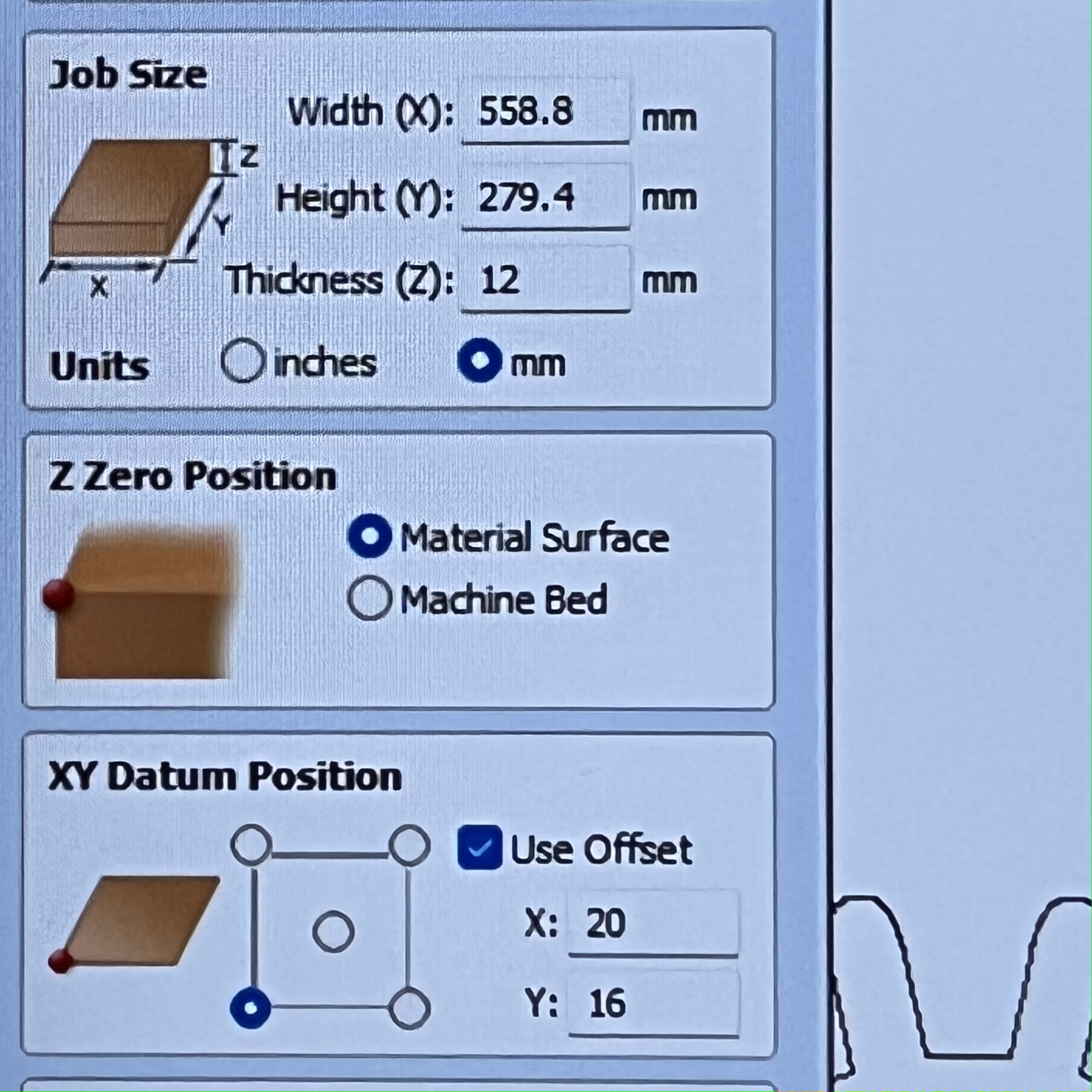
Fig 21. Job settings
Next, I added my design to the workplace.
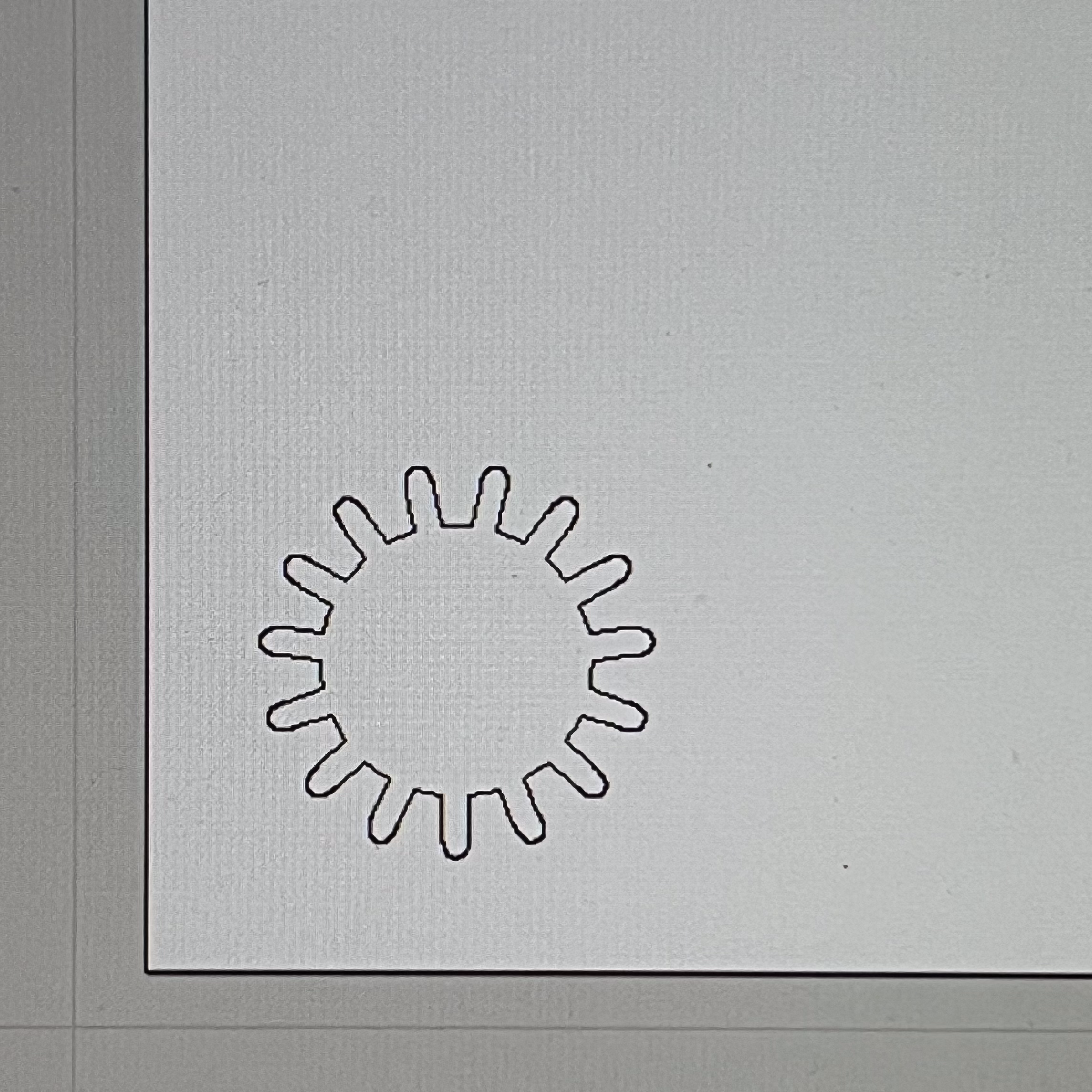
Fig 22. Aspire Workspace
After this, I joined the vectors of my project with a large enough tolerance to get 1 closed and 1 open vector.
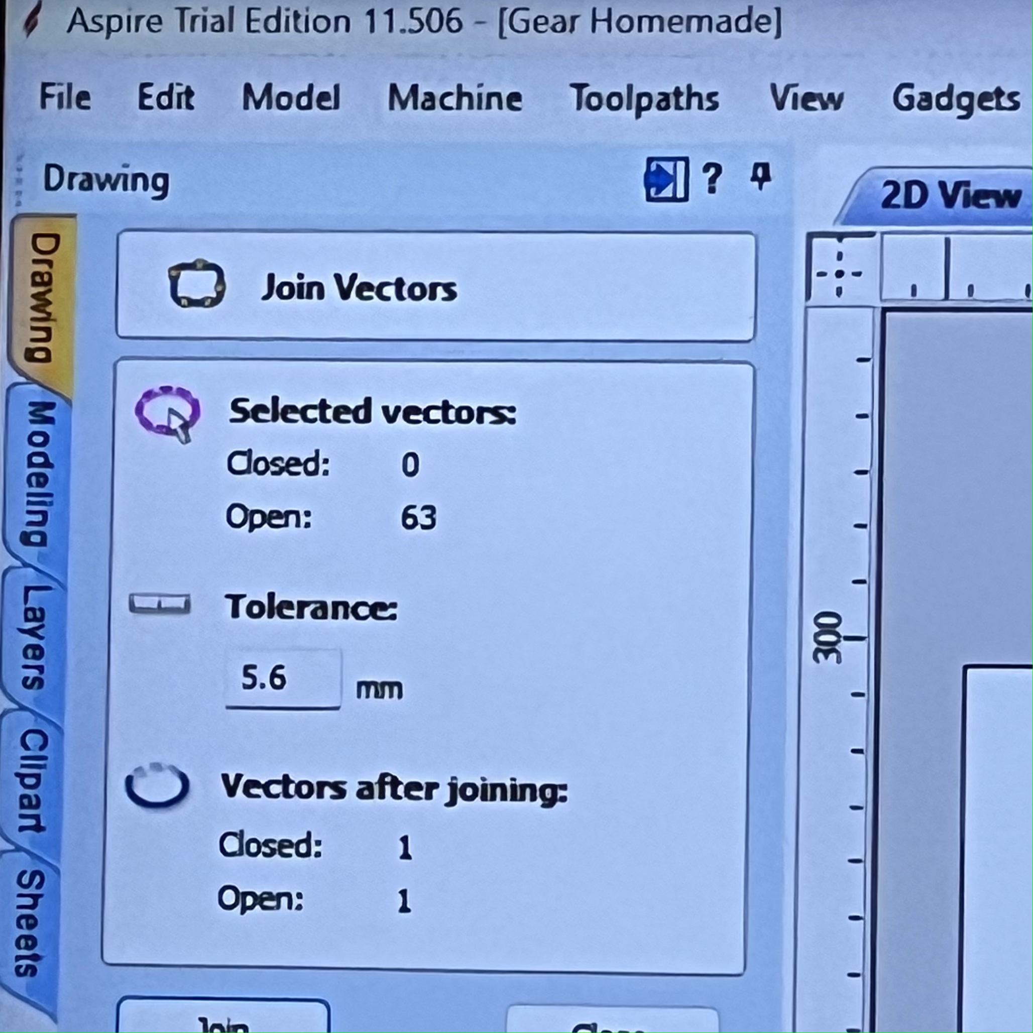
Fig 23. Joining Vectors
Finally, I created a 2D Cut Profile. I made sure that this was an outside cut to get the best dimensions possible for my gear. This yielded a 3D render of the ShopBot's path.
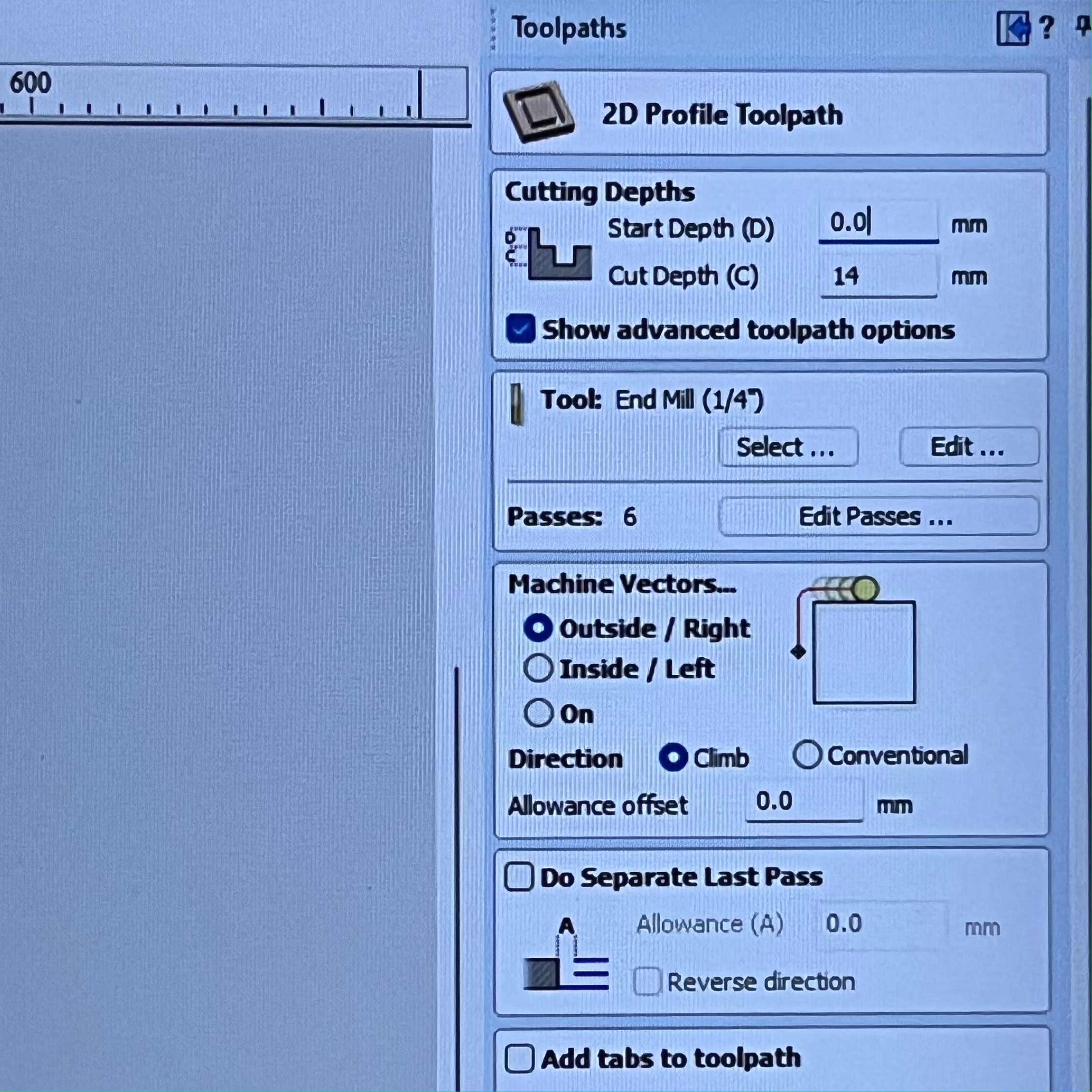
Fig 24. Cut Profile Settings
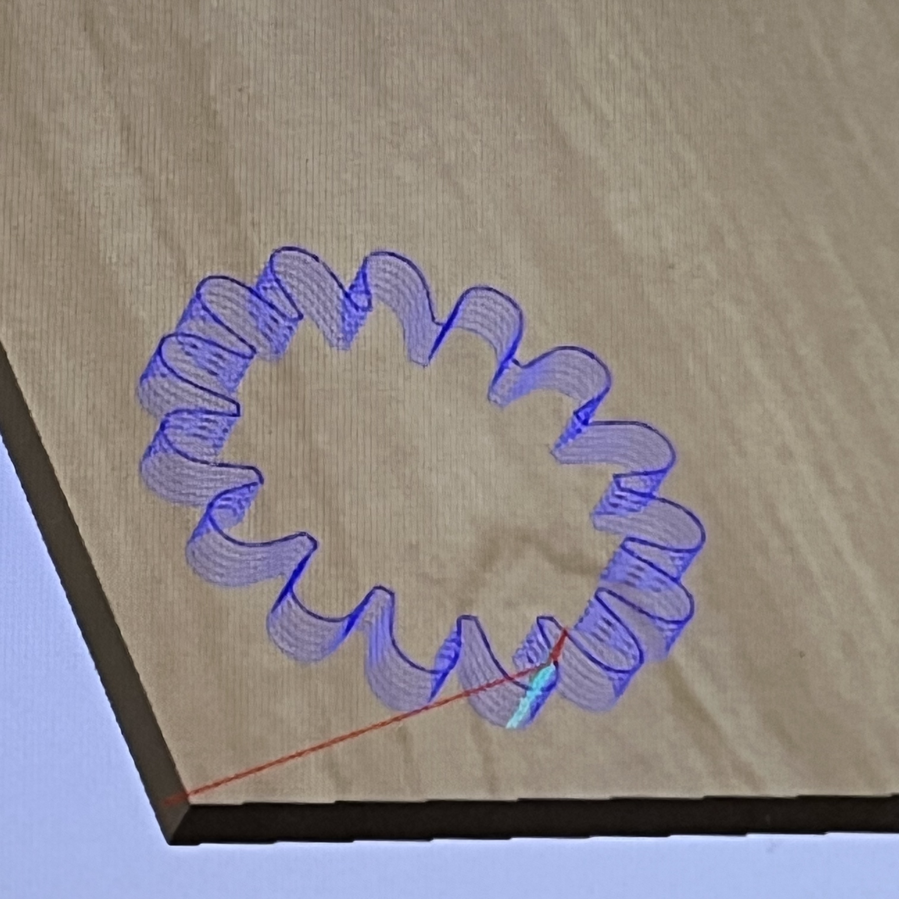
Fig 25. 3D Render
Finally, I exported it to the ShopBot Control Software and cut the piece (twice, in order to test the gears with each other).
These were the final results!
Fig 26. Final Gears
Here are the gears moving together:
Fig 27. Gears rotating
As you can see, the gears fit together perfectly! This was a great excersize with Fusion360 and a great way to learn about the advantages of CNC Milling.
Part 4 - Getting Comfortable with the Shaper
While working on my CNC project, Xander approached me and taught me how to use the Shaper. Because I was already using the ShopBot to cut my gears, I decided to cut a simple shape to become familiar with the Shaper: a beam to support my final project. I quickly created a rectangle in Fusion360 and downloaded the Fusion Extention for Shaper.
Fig 28. Fusion360 extension for Shaper
Next, I exported my design directly to the Shaper through Fusion360's Extention.
After this, I scanned the Shaper's special tape in order to give the machine a sense of position. The Shaper scans the patterns in the tape to determine where it is and cut the material accordingly.
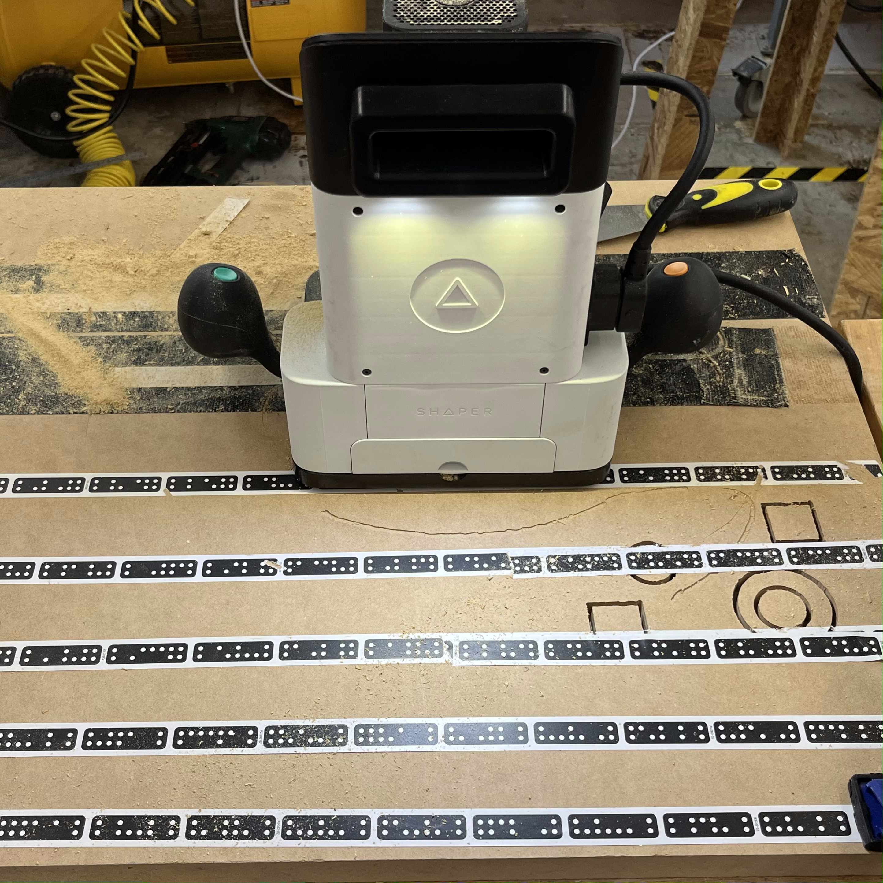
Fig 29. Laid out tape
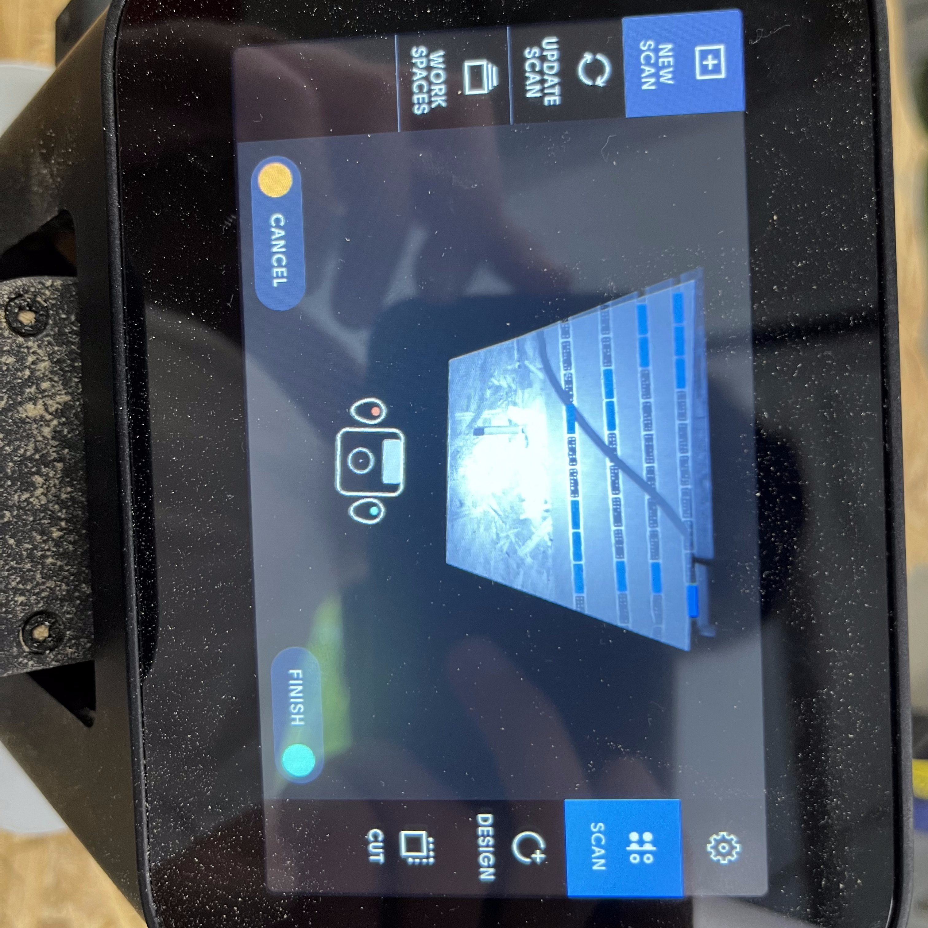
Fig 31. View from Shaper scanner
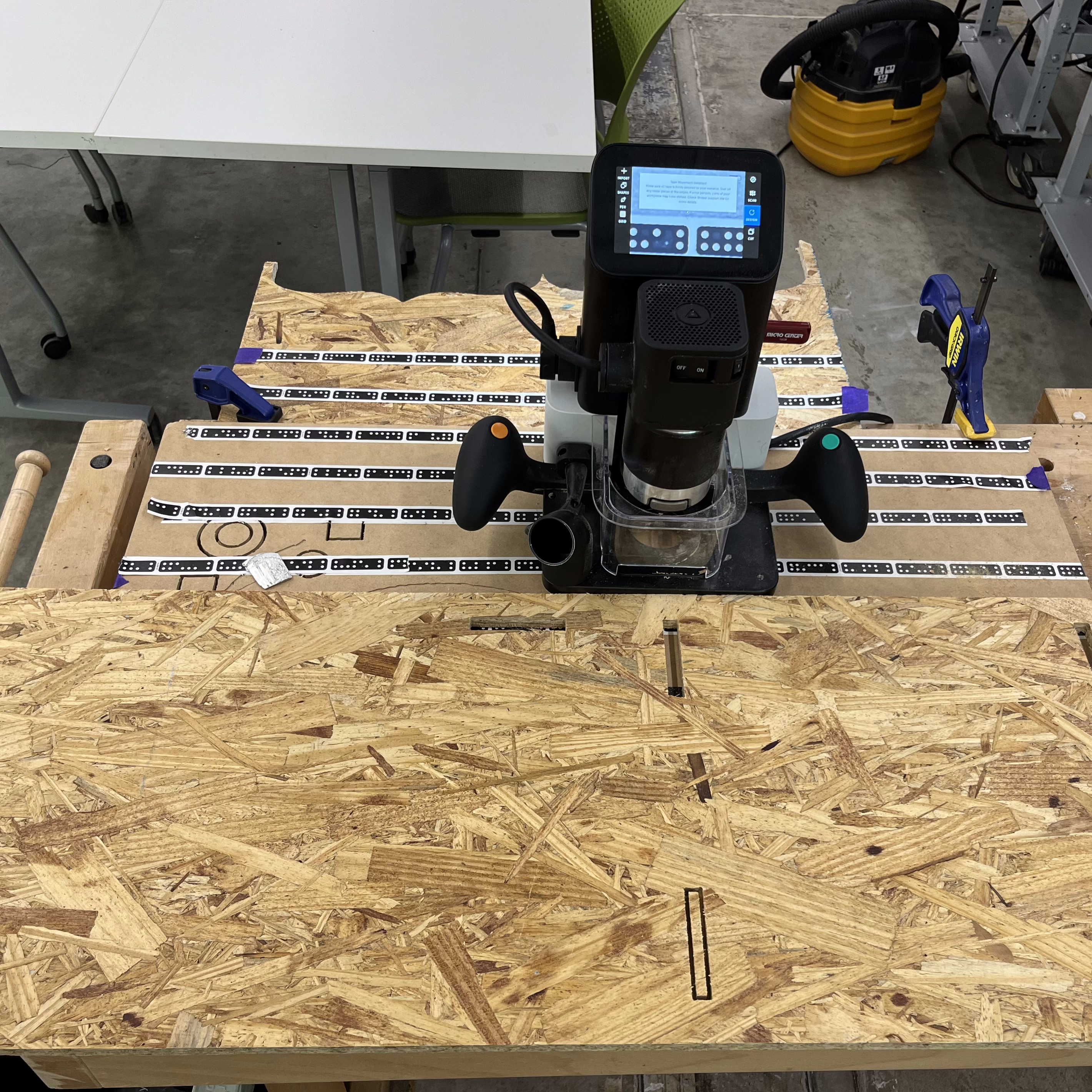
Fig 30. Full Shaper setup
I then added a board of OSB and cut my rectangle out. As you can see, the final cut was very rough in some places.
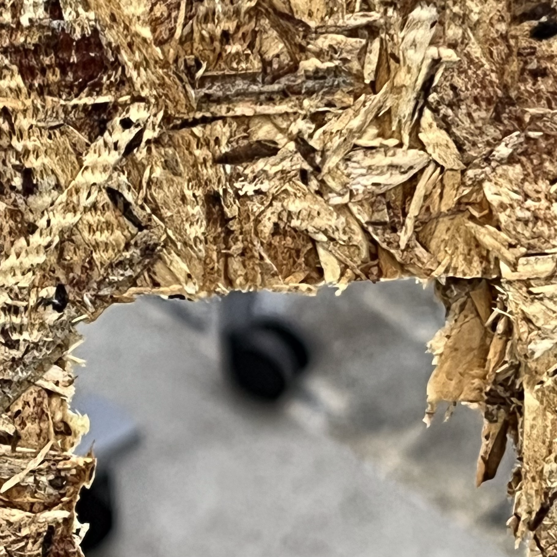
Fig 32. Frayed edge of cutout
For both this part and the part above (3), I used the belt sander to remove imperfections and yield a better product. Here are some before and after pictures.
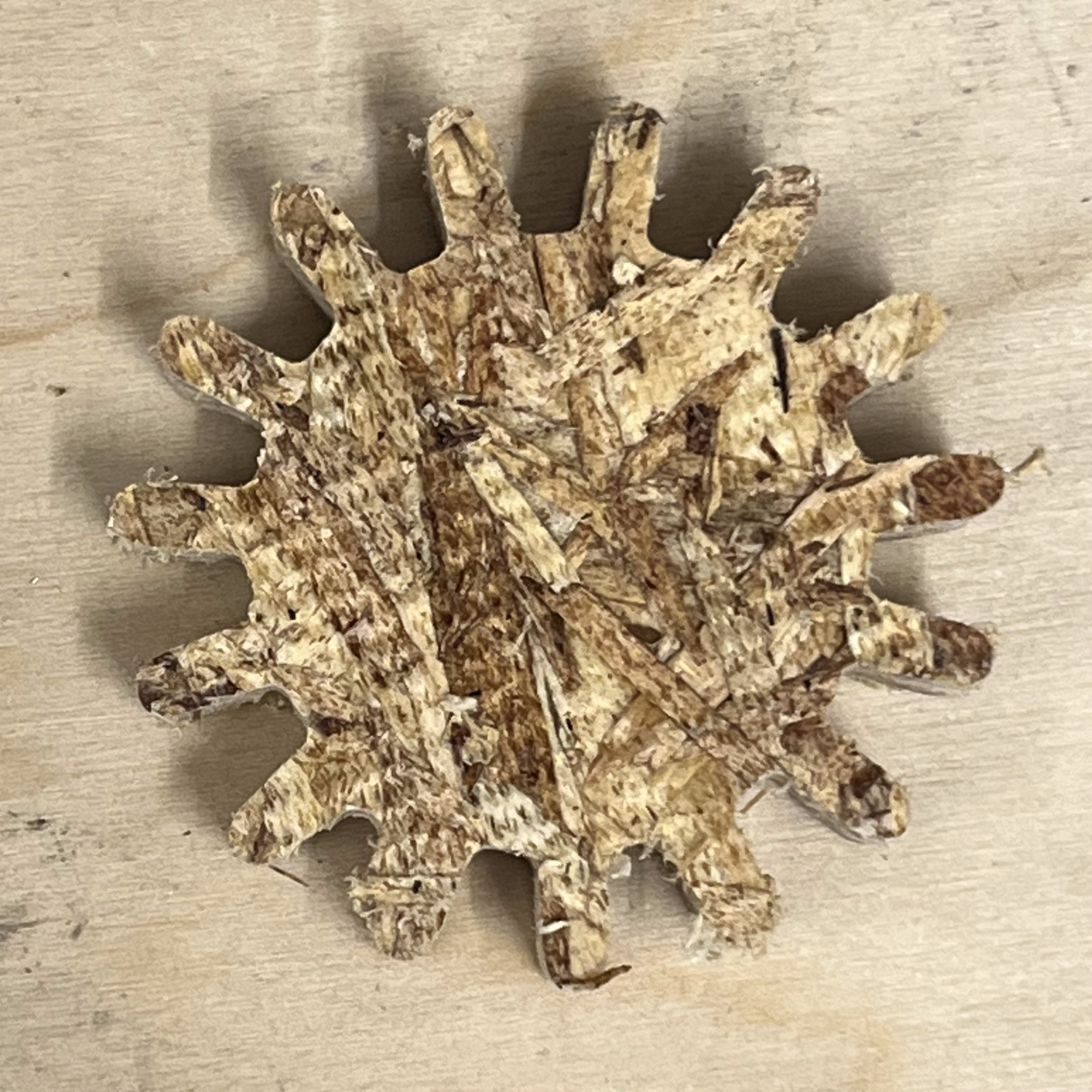
Fig 33. Gear before
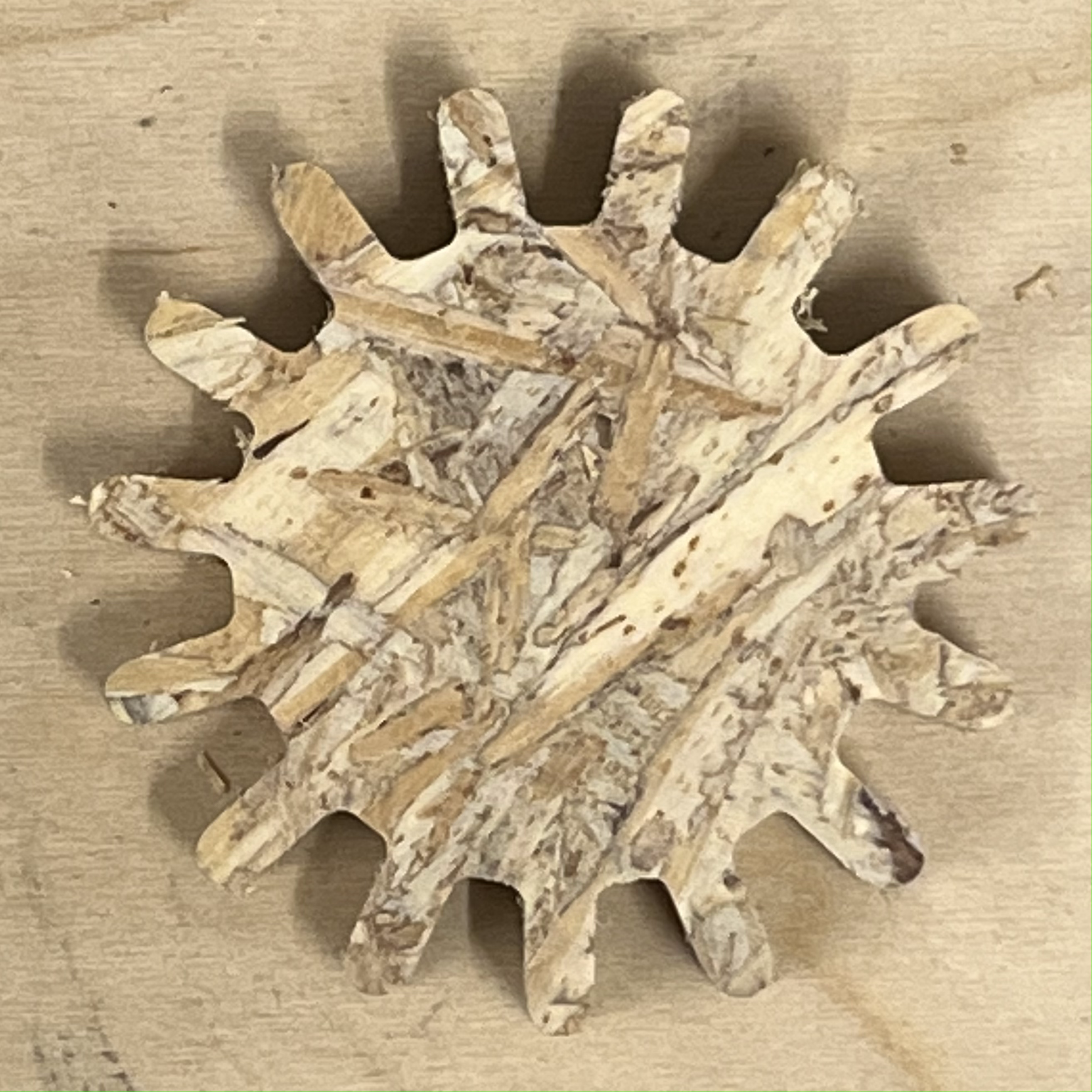
Fig 34. Gear after
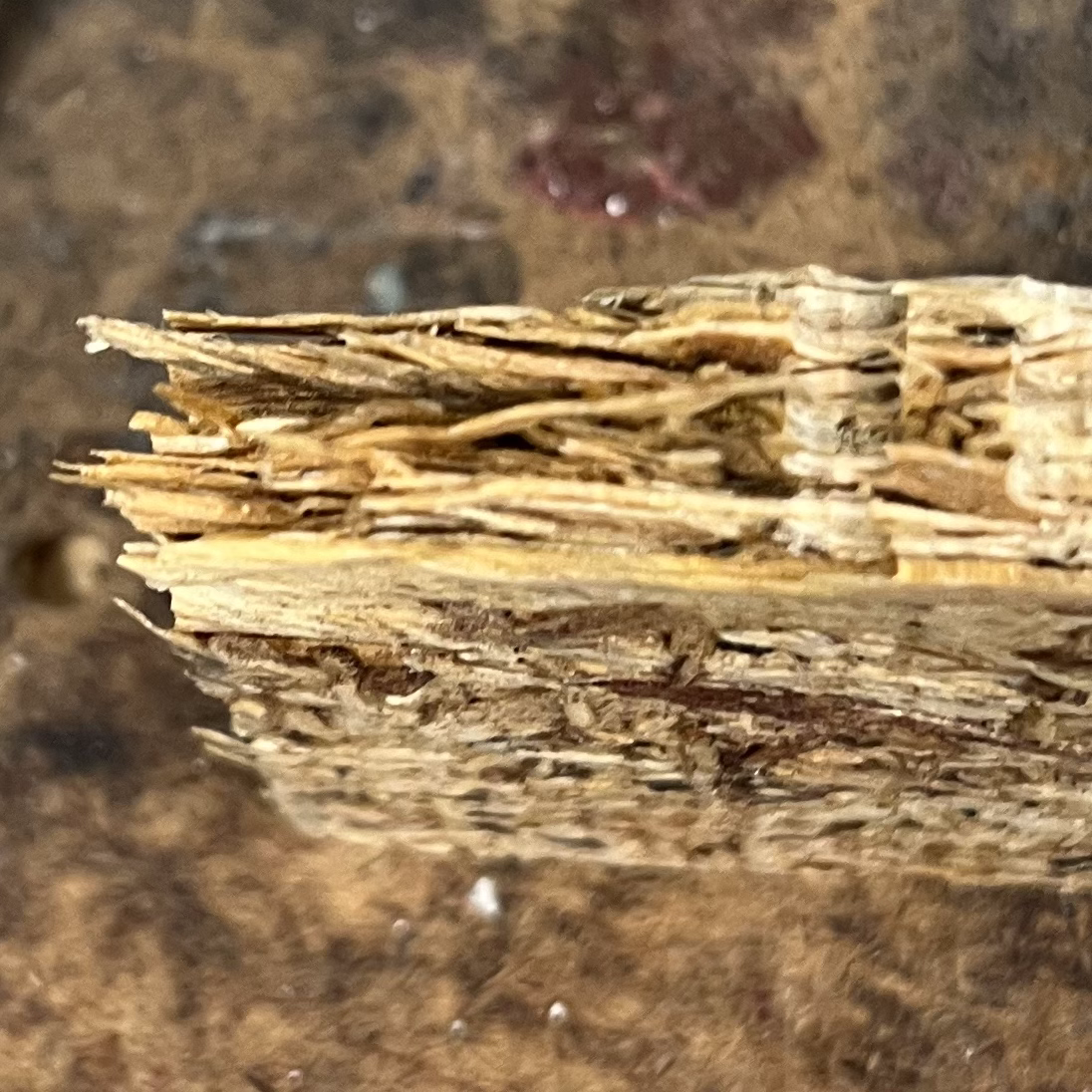
Fig 35. Beam before
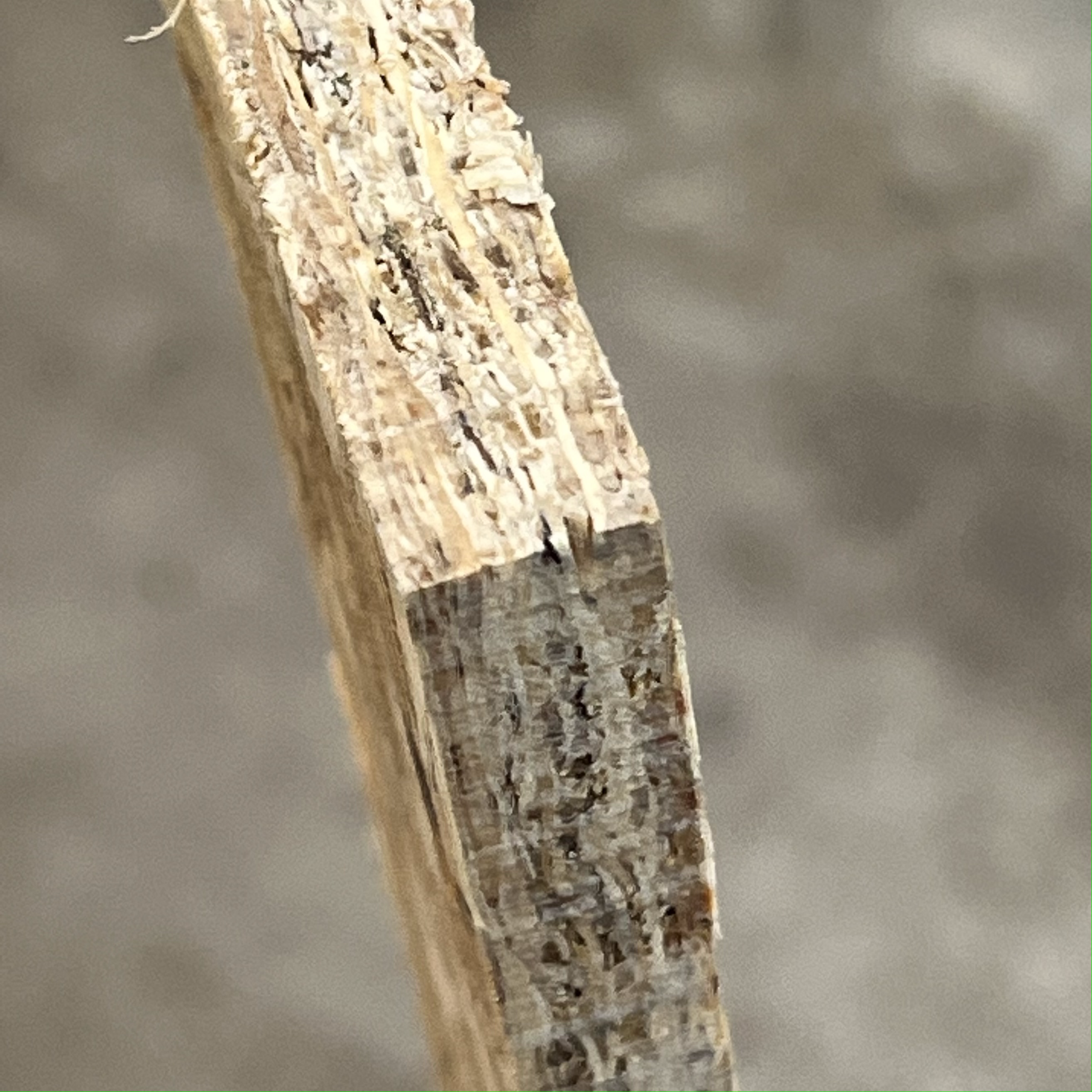
Fig 36. Beam after
This gave me a very clean final product. I definitely think the Shaper is an awesome tool that I can use in the future.
Concluding Remarks
This project gave me a lot of very valuable experience with CNC Machinery. Given that my final project operates in a similar way to some of the CNC Machines available to us, it also helped me build intuition about these systems. Additionally, my experiment in Part 1 gave me extremely useful data that I can use to produce better molds and casts in the future. I would definitely like to try out some of the other mediums (for example, metal) in my casts, although the plaster worked really well as-is.
Files Mentioned in this Document
Gear (.DXF)
Gear (.F3D)