Introduction
Today we were challenged to build our own sensor along with a capacitive touch sensor. By the end of the lesson we were supposed to be familiar with how to use voltage dividers to measure voltage drops between variable and constant resistors, as well as how to build simple capacitive touch circuits.
I am really interested in how capacitive touch technology works, and I was very excited to try using it in this project. Additionally, I wanted to expand on just a simple light sensor, and decided to make a sensor that could be used to track a source of light.
Components
This project required 2 components: the light sensor and the capacitive touch sensor.
Part 1 - Light Sensor
For my light sensor I decided to create a sensor that can identify which direction a light source is coming from. This could be useful in agricultural applications, and seemed like a really fun project. I started by designing the case for the sensor in Fusion360. This began by creating a cube with two open faces.
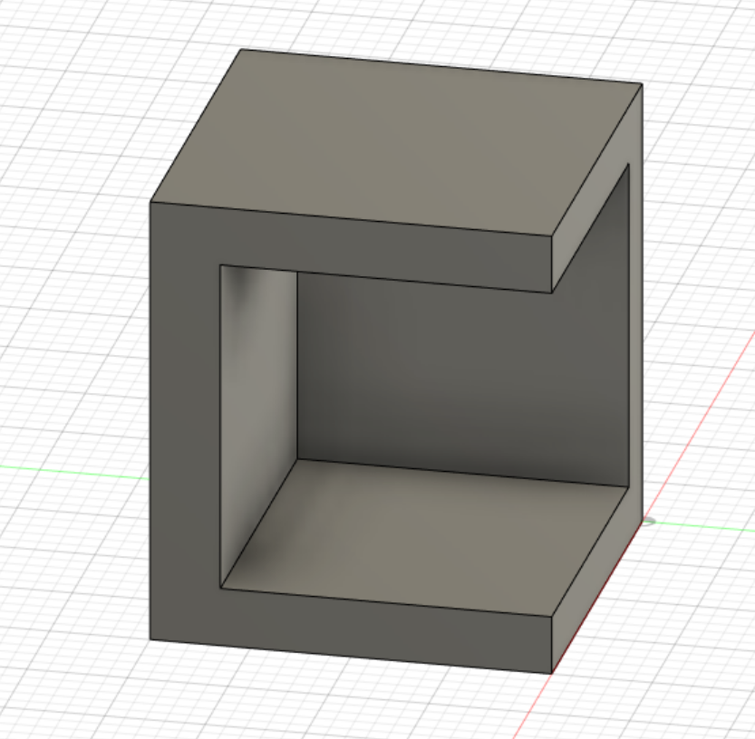
Fig 1. Cube with two open faces
Next, I duplicated this box, reflected it across the wide face, and combined it with my original box. I then sliced and printed it.
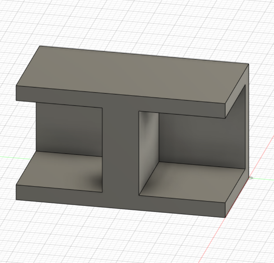
Fig 2. 2 cubes put together
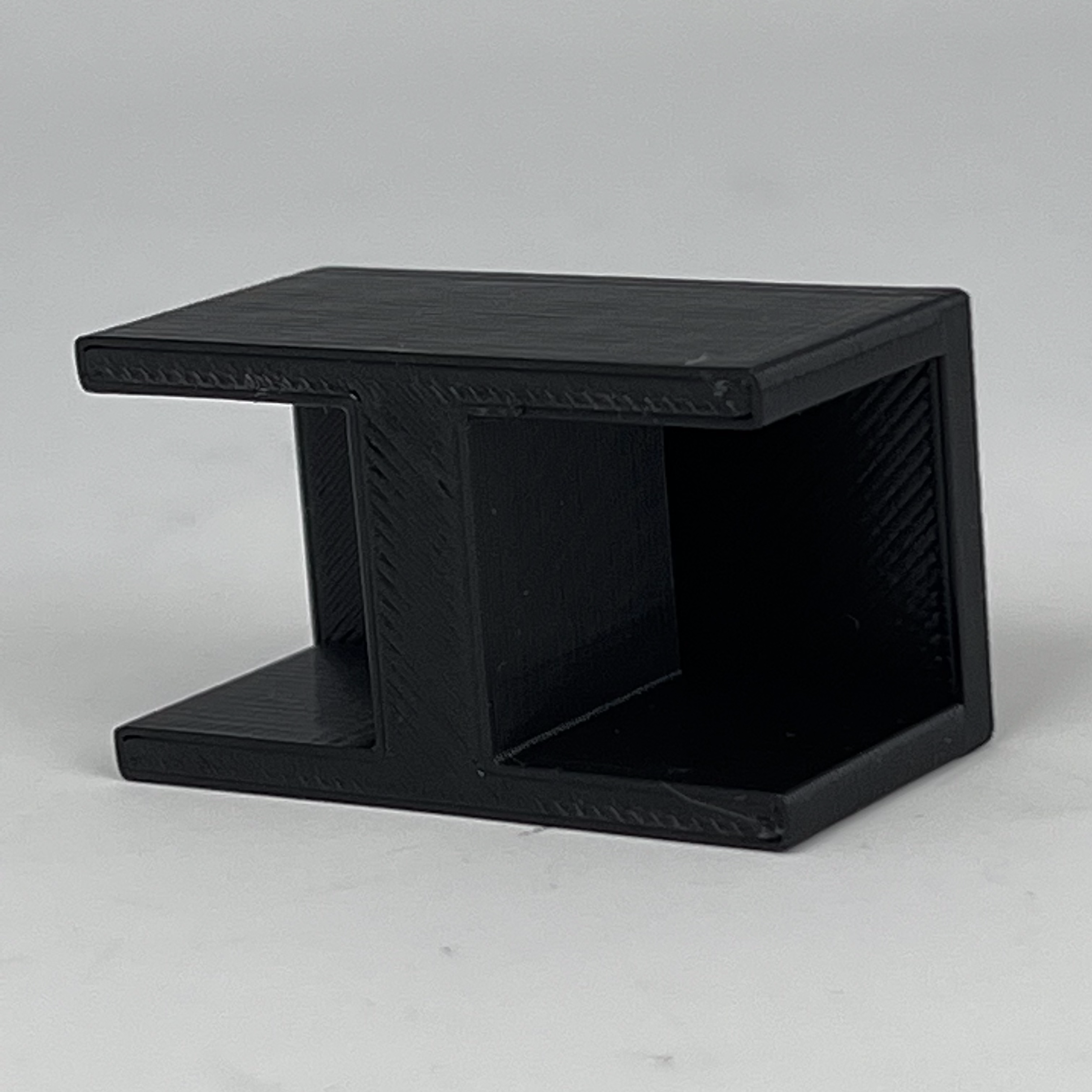
Fig 4. 3D printed case
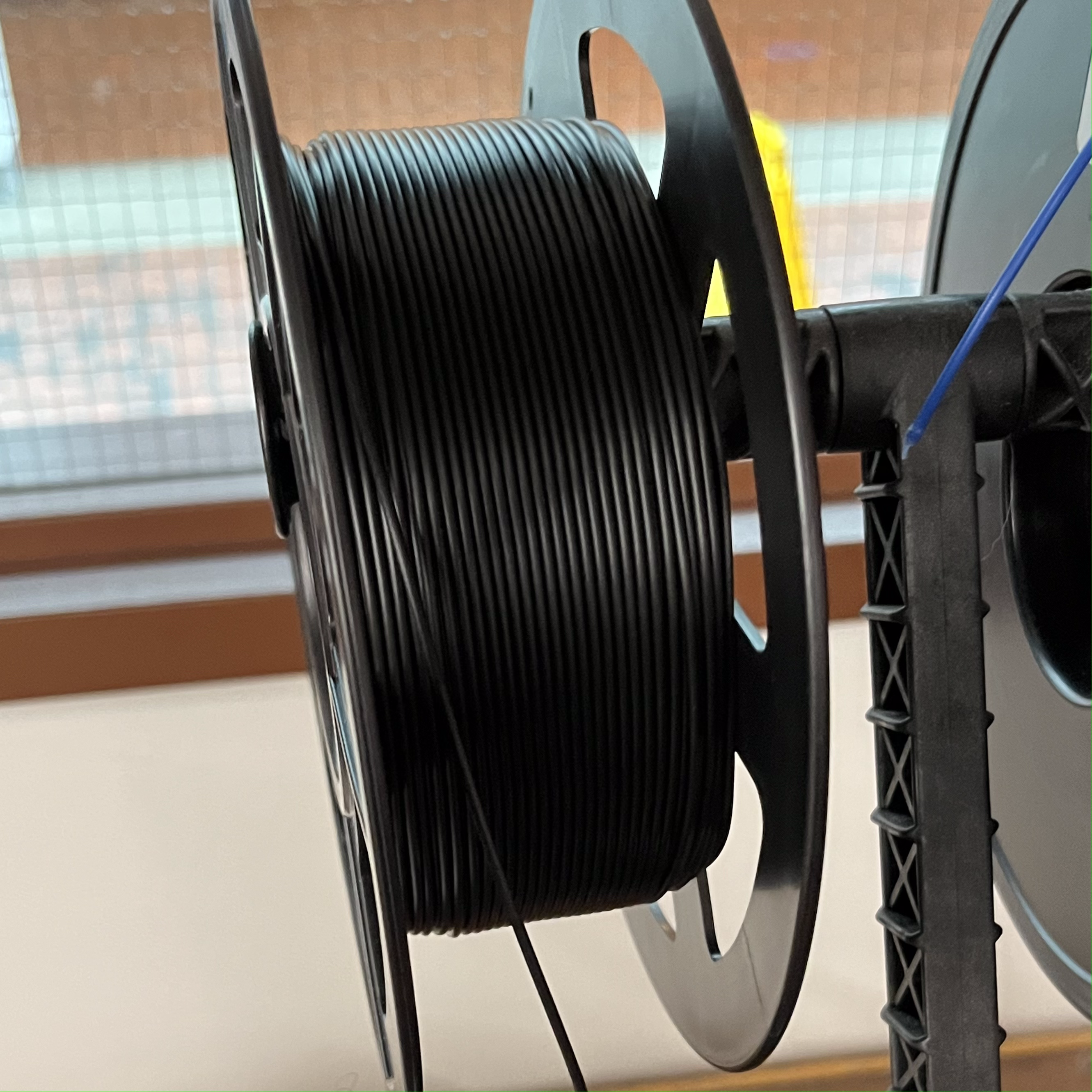
Fig 3. Loaded black filament
*Note: I used black filament to absorb the most light in an attempt to decrease noise. I then drilled pairs of small holes into each box and pushed a photoresistor through each pair.
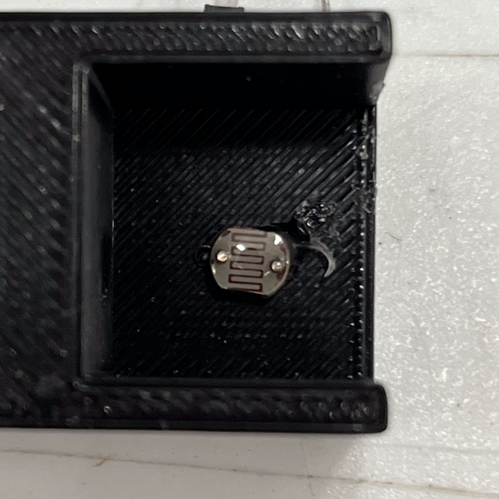
Fig 5. A photoresistor in one of the cubes
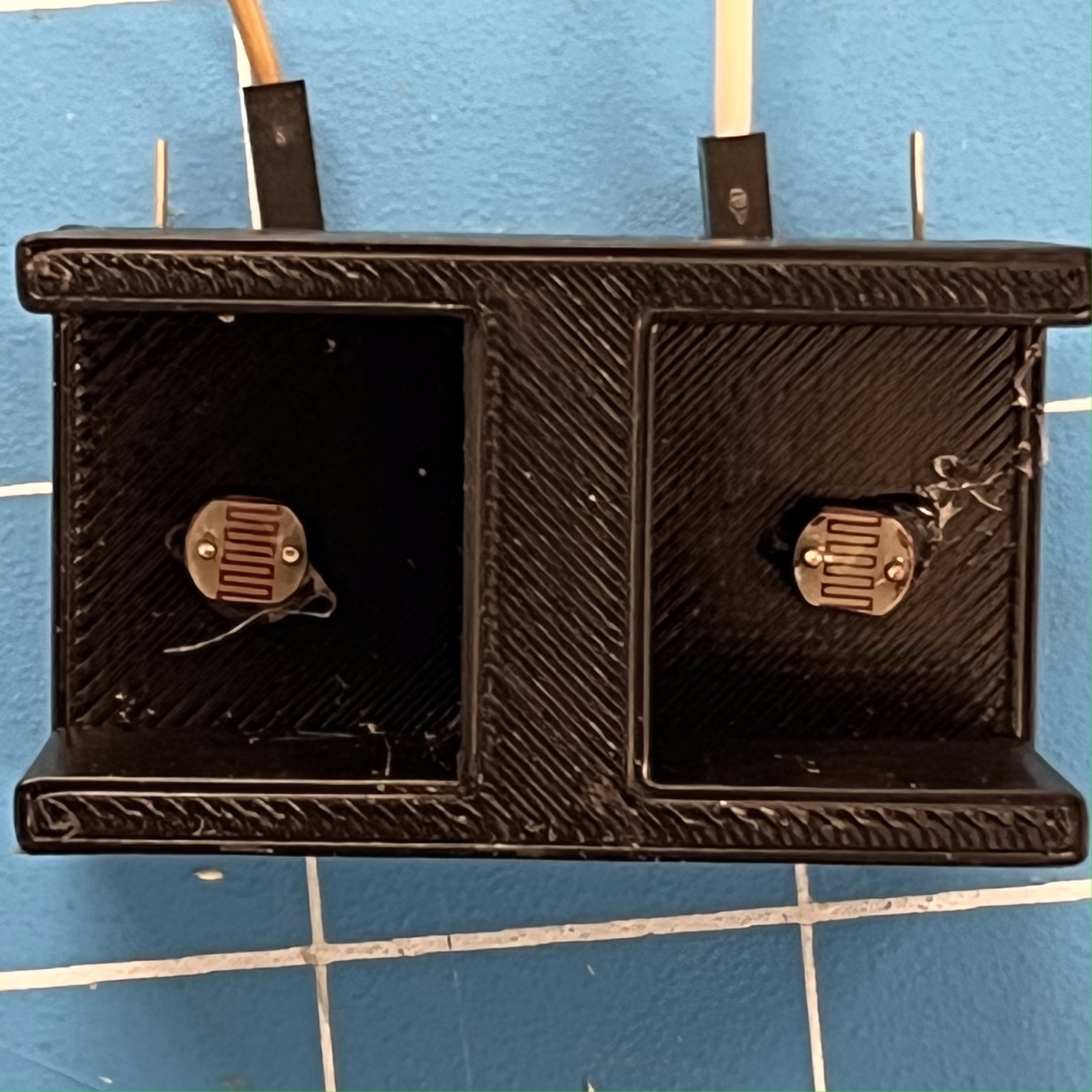
Fig 6. Both photoresistors in place
Finally, I soldered a 10k resistor to both of the photoresistors, with a wire at this junction.
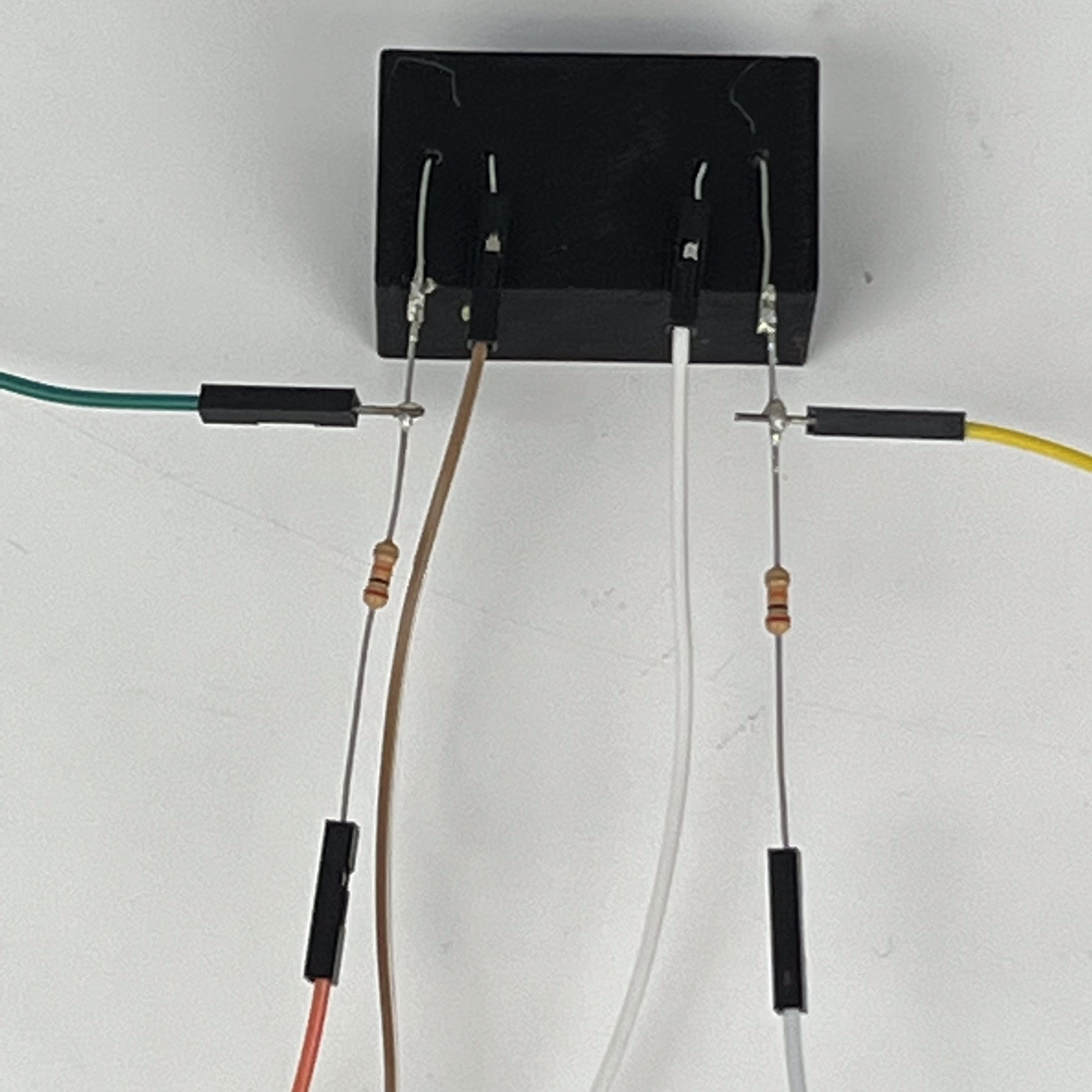
Fig 7. Wiring for the light sensor circuit
Now I was able to wire my sensor to the Arduino. I started by wiring the 10k resistors to the 3V output pins, the wires at the junctions to pins 9 and 10, and the free ends of the photoresistors to ground.
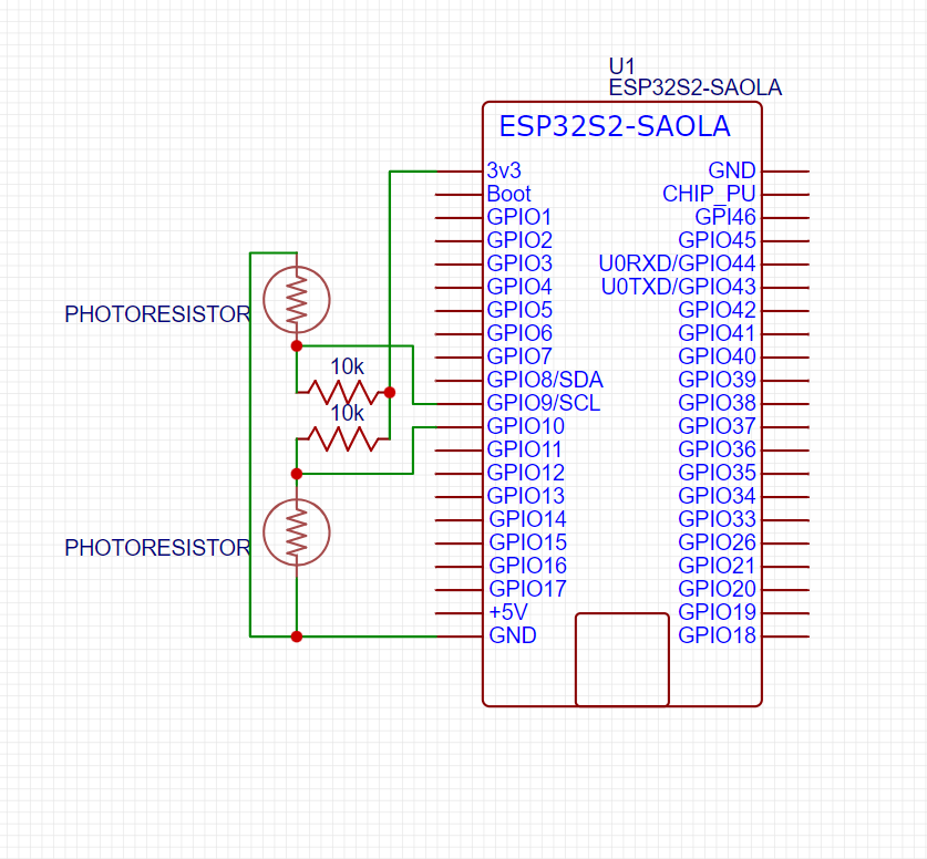
Fig 8. Circuit diagram
I then began writing the code required to get useful data from the sensor.
Code:
As you can see, I created a class to represent a single photoresistor. I then instantiated two instances of this class: one for each side of the sensor. Finally, I read the data from these sensors every 100ms.
Using my iPhone 11's flashlight setting in a room with no lights or windows, I measured the data I got at different distances (5 and 30.5cm) and angles (90 degrees represents center) and averaged over 20 cycles. The data is displayed below.
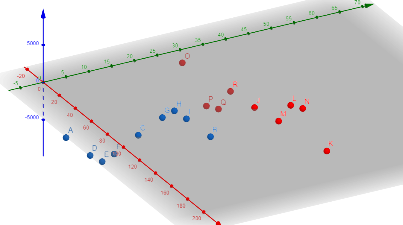
Fig 9. Collected data (deg:dist:val | r:g:b)
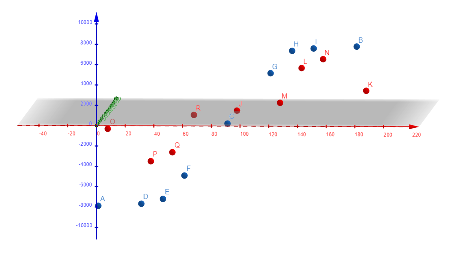
Fig 10. Collected data
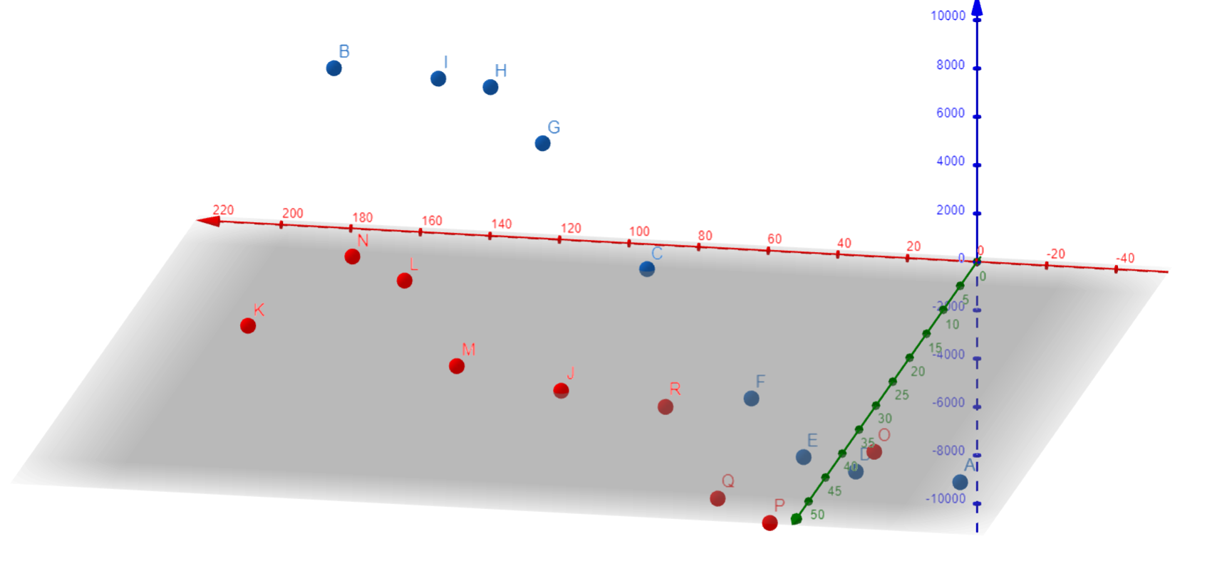
Fig 11. Collected data
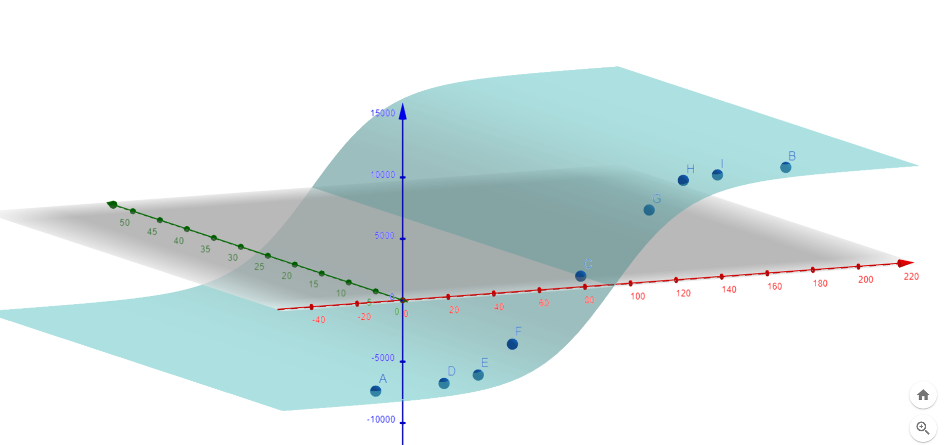
Fig 12. Fitted curve to 5cm
This data is clearly more consistent and has a smoother range at 5cm, so I will continue to work with this as my sensor's "optimal" range.
I quickly fitted a curve to my 5cm data: output = (16122/(1+e^(-0.06(x-90))))-8137. This equation can be used to interpolate the results that will be found between 0 and 180 degrees.
In order to calibrate my sensor, I first need to determine a range of degrees that can be considered "center". I decided that 85-95 degrees was a fair range, and used my equation from above to determine that this meant the output must be between -1276 and 1124. This gave me my new code:
Code:
This code worked perfectly, giving me adjustments whenever I strayed too far off course.
Part 2 - Capacitive Touch Matrix
After my recent frustrations using the MPU6050 Gyroscope for my final project, I wanted to experiment with capacitive touch as a potential input device for my final project. For this I would need to determine the exact position of a grounded object within the matrix.
To start, I designed and cut a 7x7in square of plywood.
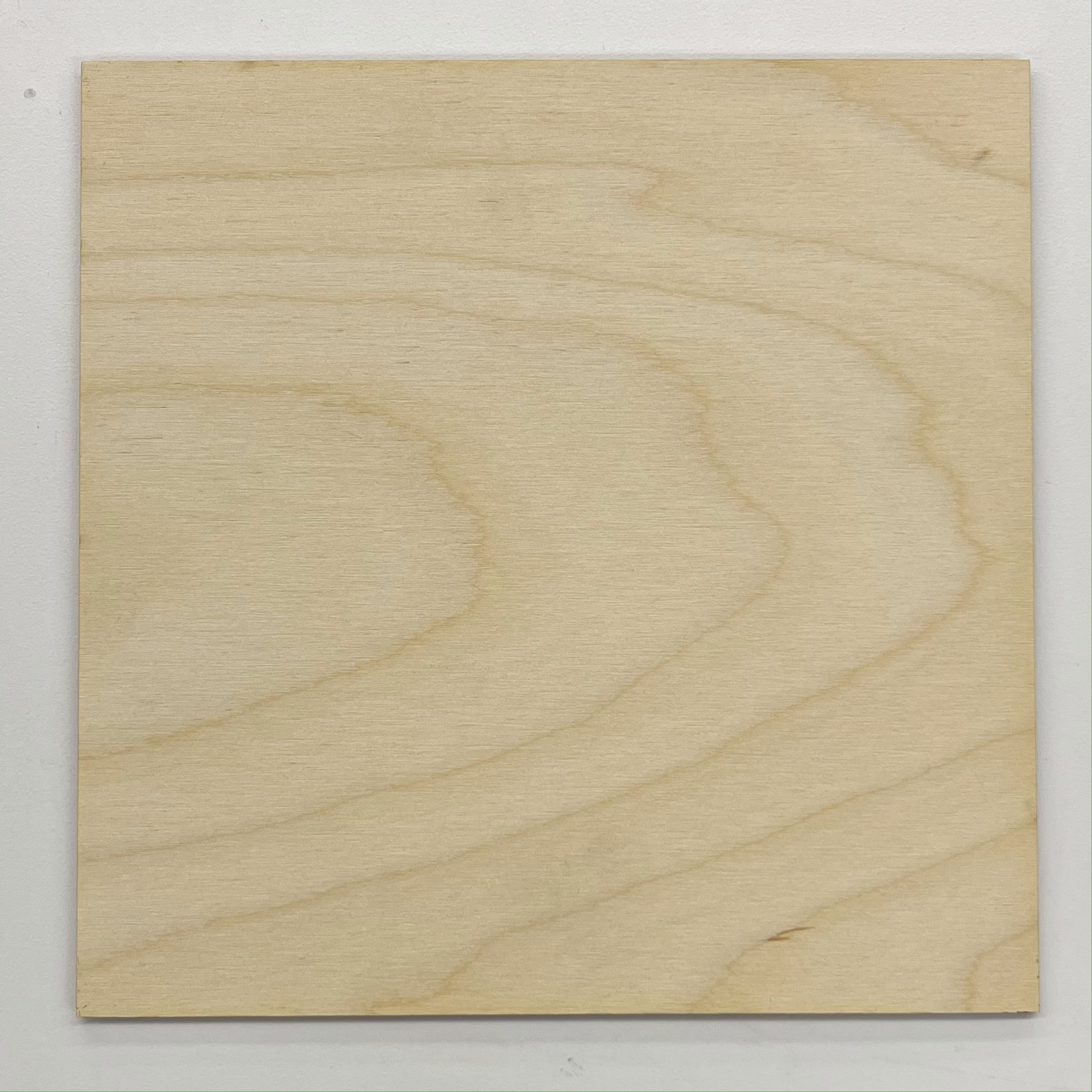
Fig 13. 7x7in board
Next, I marked copper tape at 1in intervals and cut it using the paper cutter.
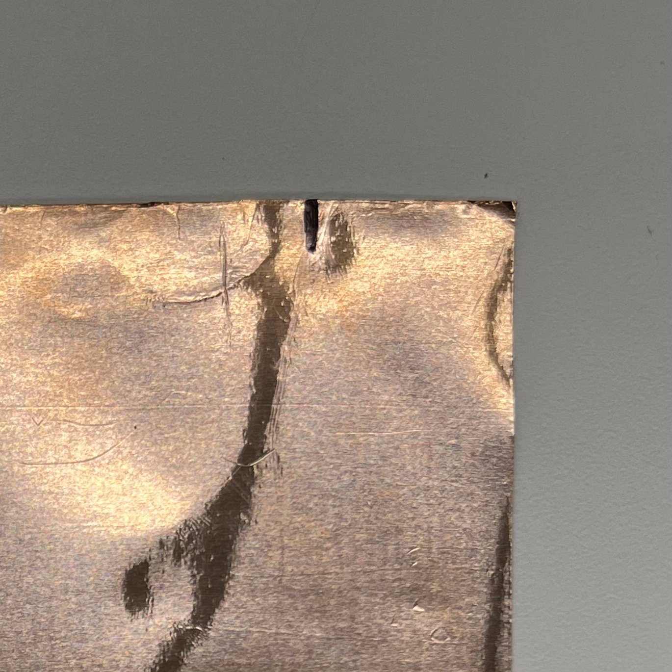
Fig 14. Marked copper tape
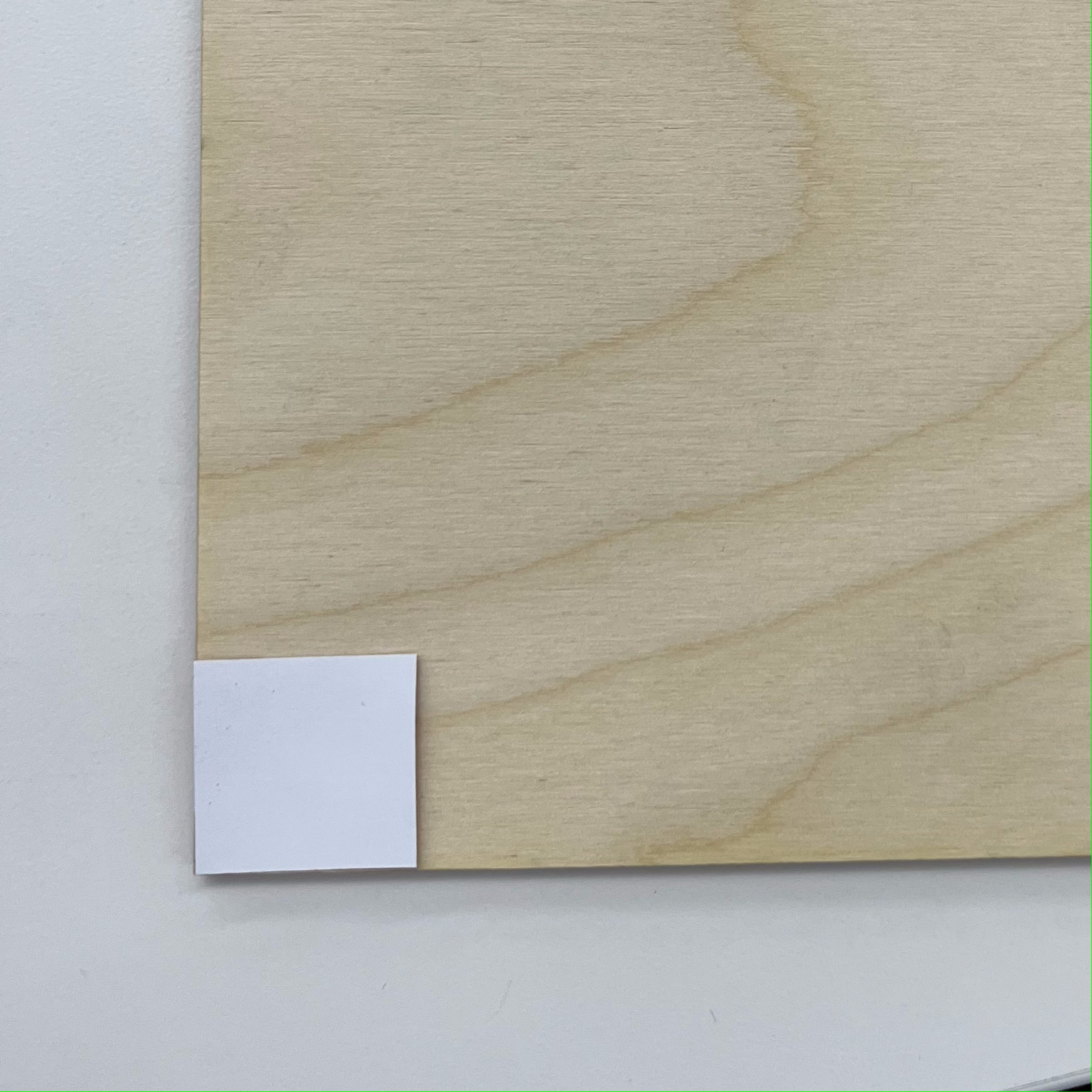
Fig 15. A square of copper tape on board
I then added added one of these squares to the plywood, soldered a wire to it, and covered the solder with copper tape.
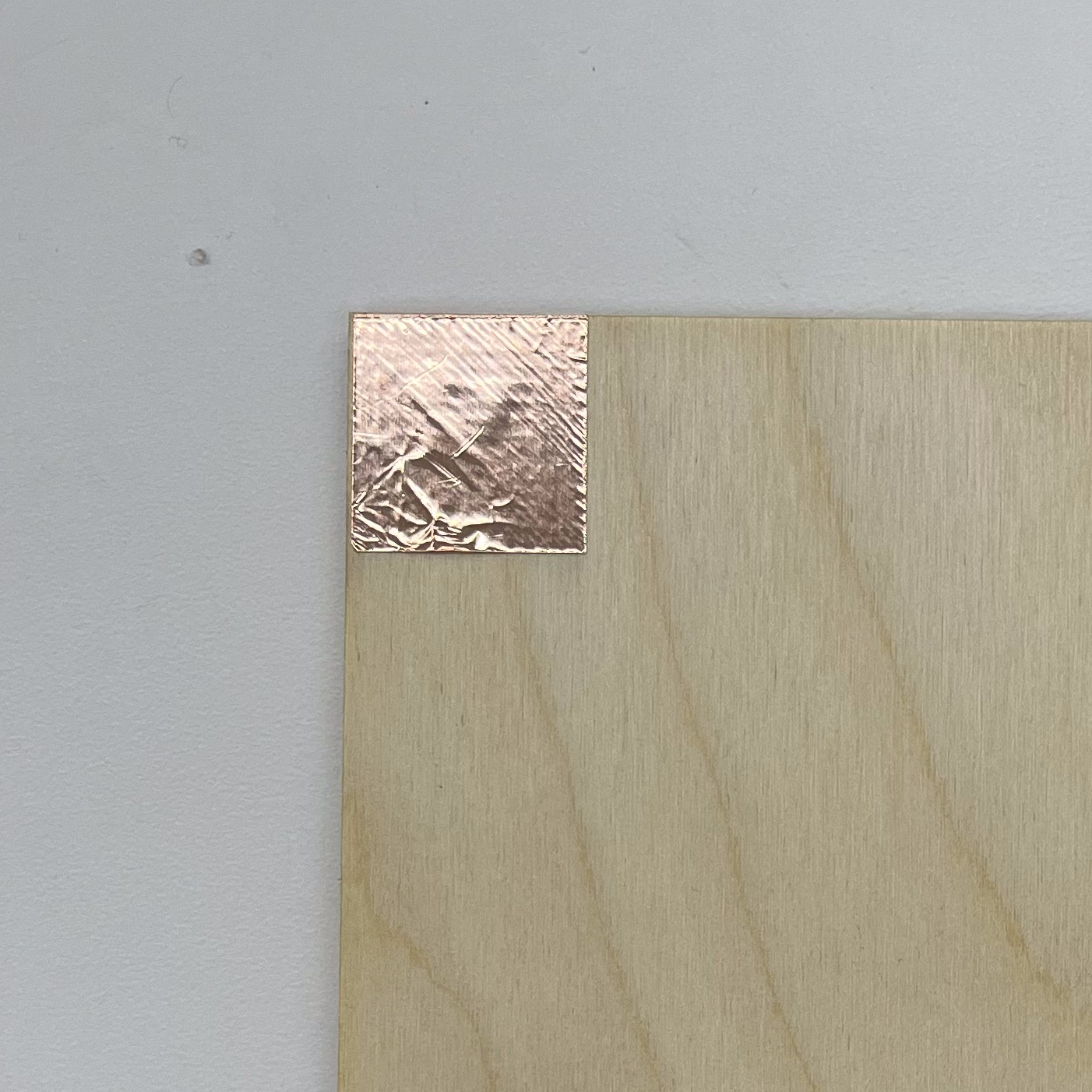
Fig 16. Copper tape stuck on board
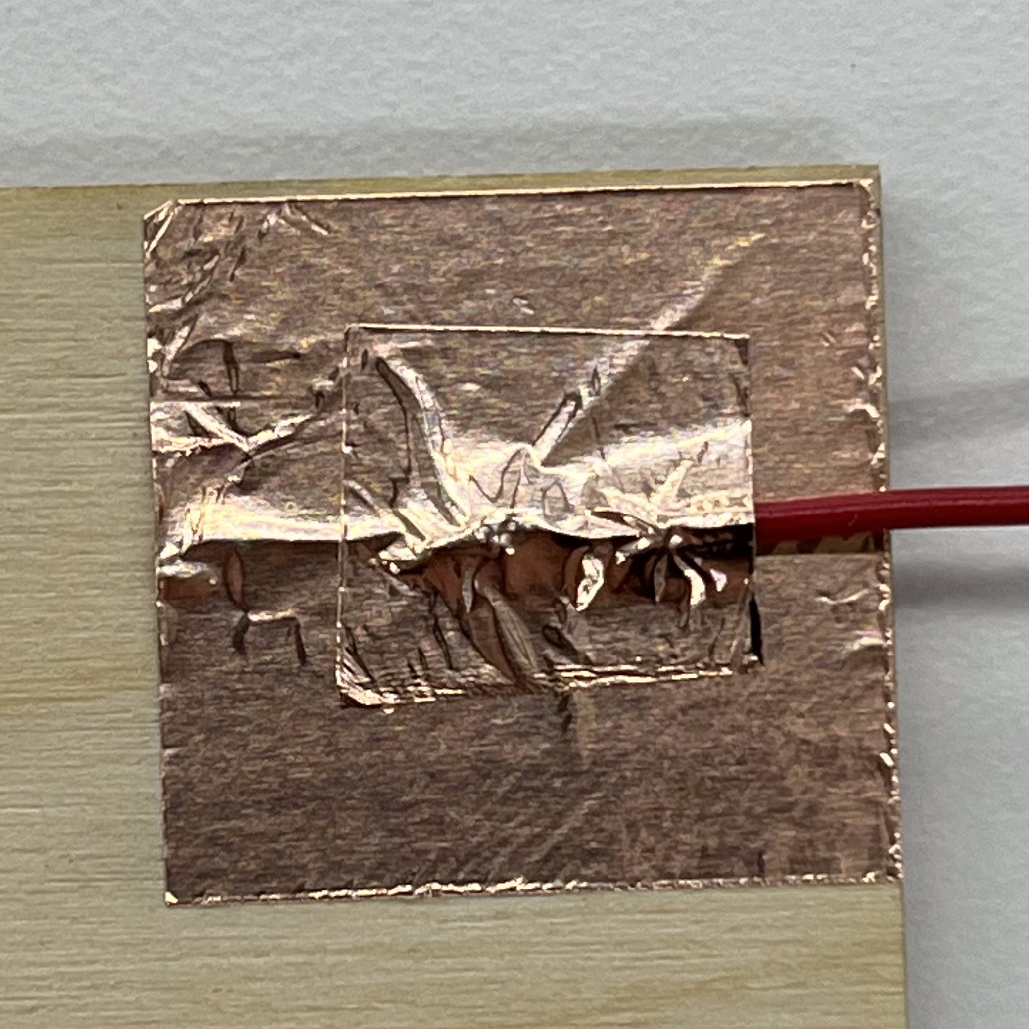
Fig 18. Solder joint covered with copper tape
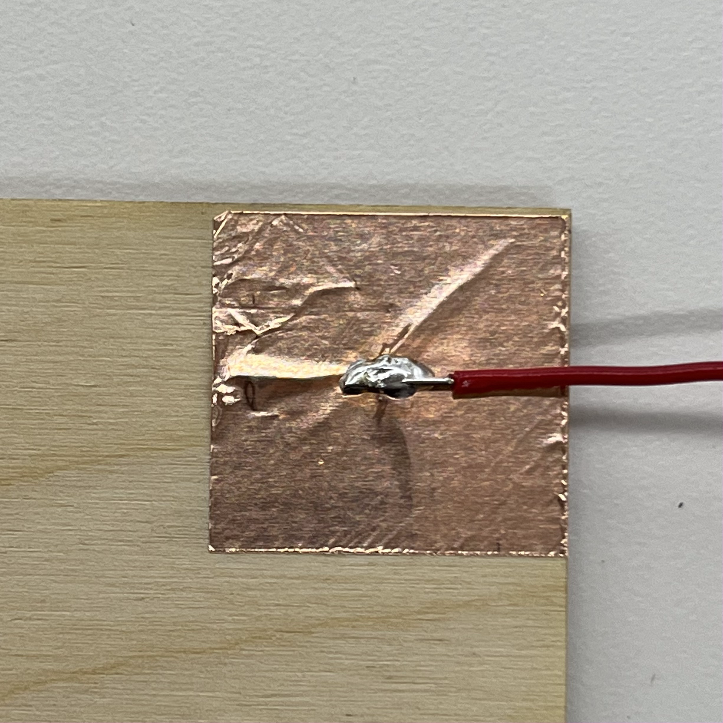
Fig 17. Wire soldered to copper tape
Finally, I repeated this with the remaining 11 squares (3 squares in the center were used for testing).
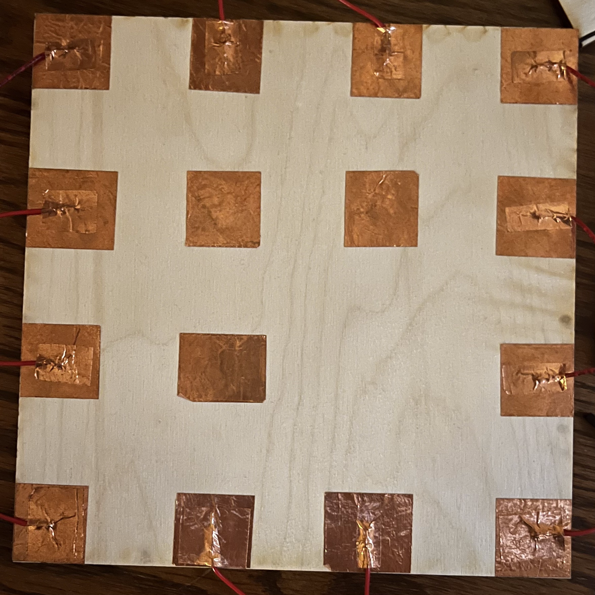
Fig 19. Final board
I now had a matrix of 12 capacitive touch pads, and I wired 4 of them up to 100k resistors connected to GPIO pins 1-4. I then wired the back plate made of aluminum foil to GPIO pin 42 and made the following code:
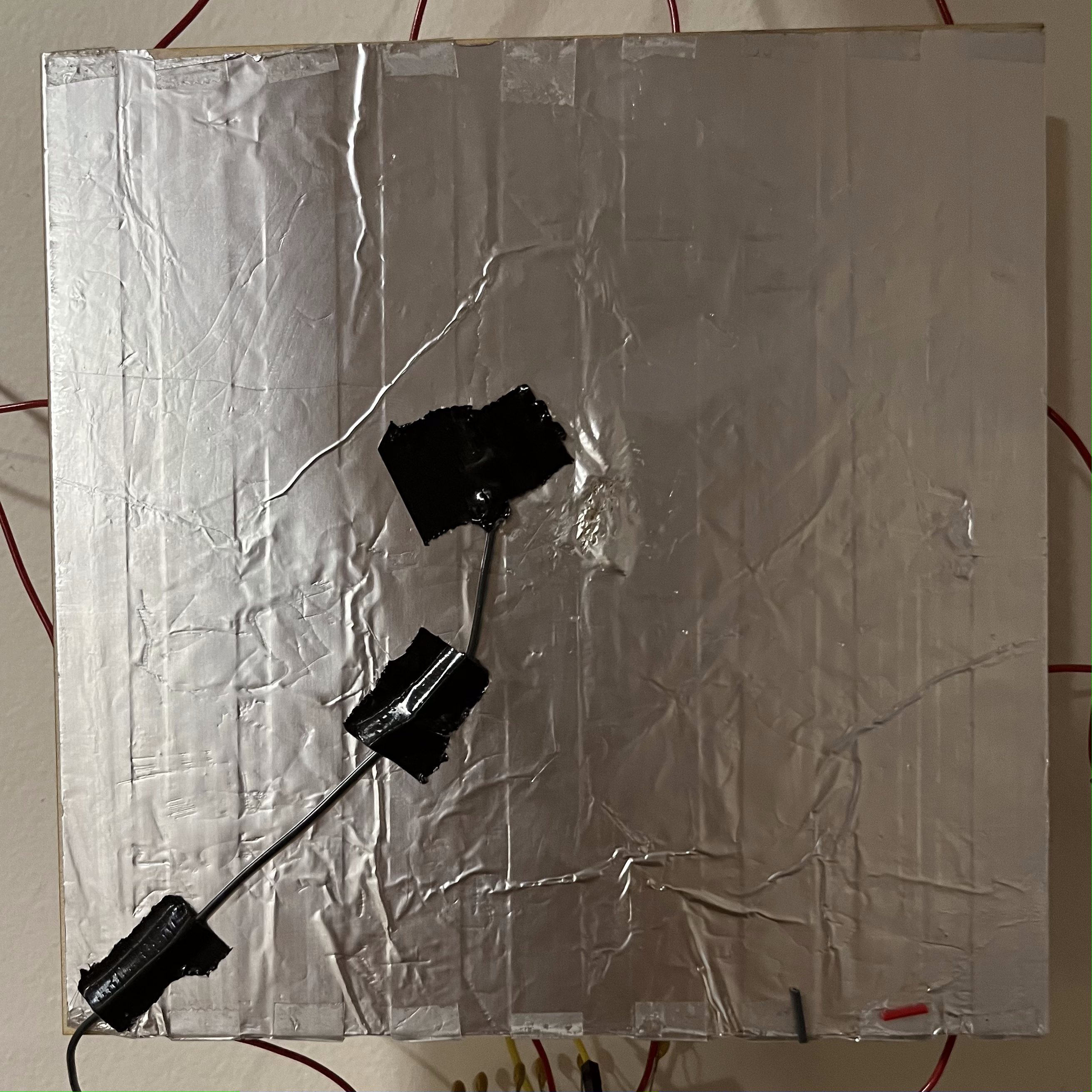
Fig 20. Tin foil backing
Code:
As you can see, this code is extremely similar to the code from Part 1. I create a class to represent a single capacitive cell and instantiate 4 of them along with defining tx_pin. I then sum the difference between the high and low readings of the capacitive cells over 100 cycles. In my testing, there was a clear trend between the proximity between my finger and a given capacitive cell, and its reading. I decided to measure these readings from various distances with one cell. This is the data I collected, averaged over 5 tests.
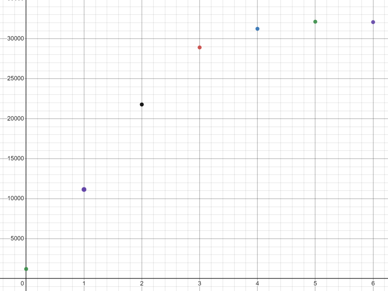
Fig 21. Collected data (dist:val | x:y)
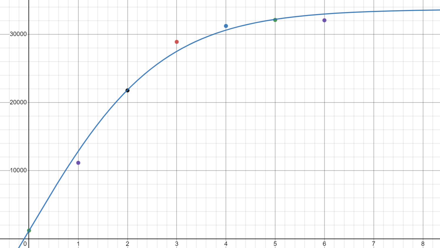
Fig 22. Fitted curve to collected data
After plotting the data and fitting a curve to it ((65000/(1+e^(-0.75x)))-31286), I am able to see that I can likely rely on a given capacitive cell to determine distances within 3cm. Because my cells are placed 2.54cm apart, I believe that this will allow me to determine the location of a grounded object with acceptable accuracy, although significantly more testing is required.
Concluding Remarks
This project gave me a lot of experience with fitting curves to data and using those curves to determine an acceptable range of measurements. I anticipate that my input device will be the most difficult aspect of my final project, but I believe this project left me well-equipped for the challenge. I was also able to get a lot of experience with capacitive touch which is a technology that I would love to incorporate in my final project.
Files Mentioned in this Document
Photoresistor Reader (.INO)
Capacitive Touch (.INO)
Photoresistor Case (.STL)
Photoresistor Case (.GCODE)