Introduction
Today we were challenged to program an Arduino to control something and make a diagram of the circuit we used. By the end of this lesson we were supposed to know how to use and program an Arduino, build simple circuits, and drive motors using an H-Bridge.
I have always loved programming microcontrollers, often playing around with my Raspberry Pi at home. I have never used an Arduino before, and wanted to use one to create a light display. Drawing inspiration from the many signs I have seen using moving lights as an attention-getter, I set out to make a series of lights "move" in a wave pattern.
Components
This project required 3 components: the Arduino, the circuit, and the program to tie the two together.
Part 0 - Setting up the Arduino IDE
I had an extremely difficult time setting up the Arduino ESP32-S2 in the Arduino IDE. Now that I solved it, I feel as though it is a significant part of my project and is worth documenting for others.
To begin, open the Arduino IDE and click on "Tools".
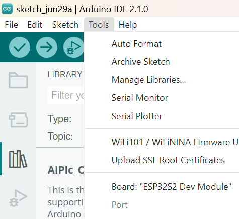
Fig 1. Tools tab
Then go to "Board", and download "esp32".
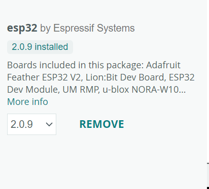
Fig 2. Downloading "esp32"
Then select "ESP32S2 Dev Module as your working board.

Fig 3. Selecting the working board
Finally, make sure that the USB connection is in the port shown below. If it is not, the Arduino IDE will not recognize that there is a board being used.
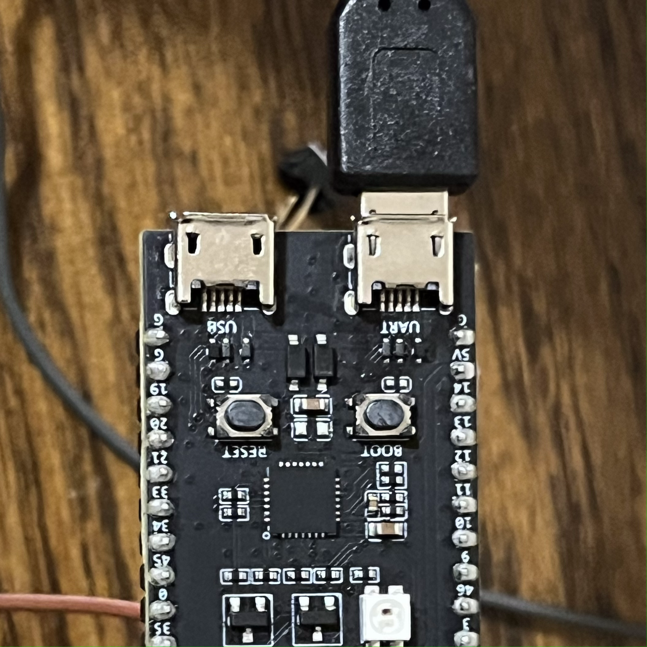
Fig 4. Proper port for ESP32
Part 1 - Moving Light Circuit
In order to make the moving light circuit, I needed to first work on making multiple lights blink on and off. I started off by attatching the LEDs and the ground.
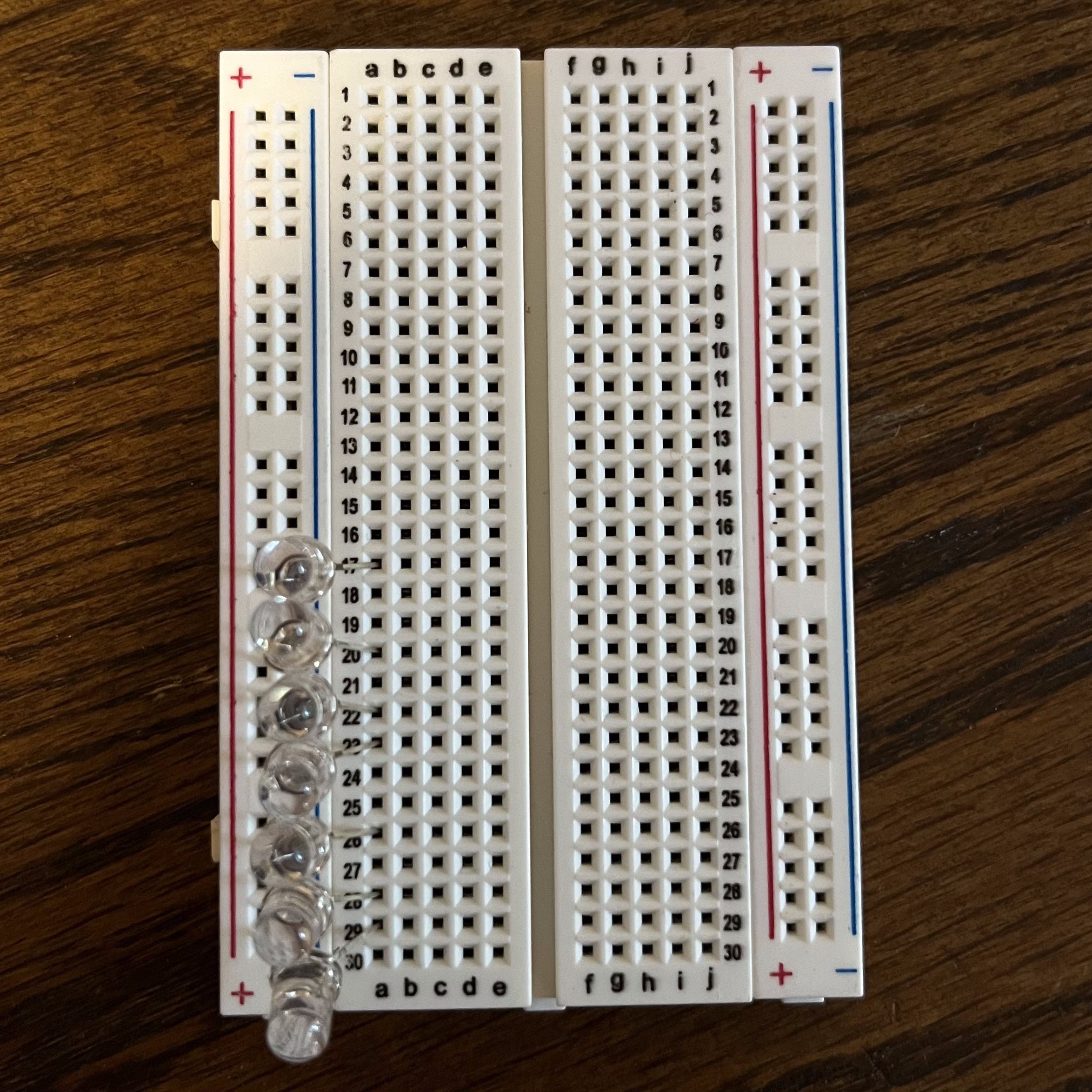
Fig 5. LEDs lined up
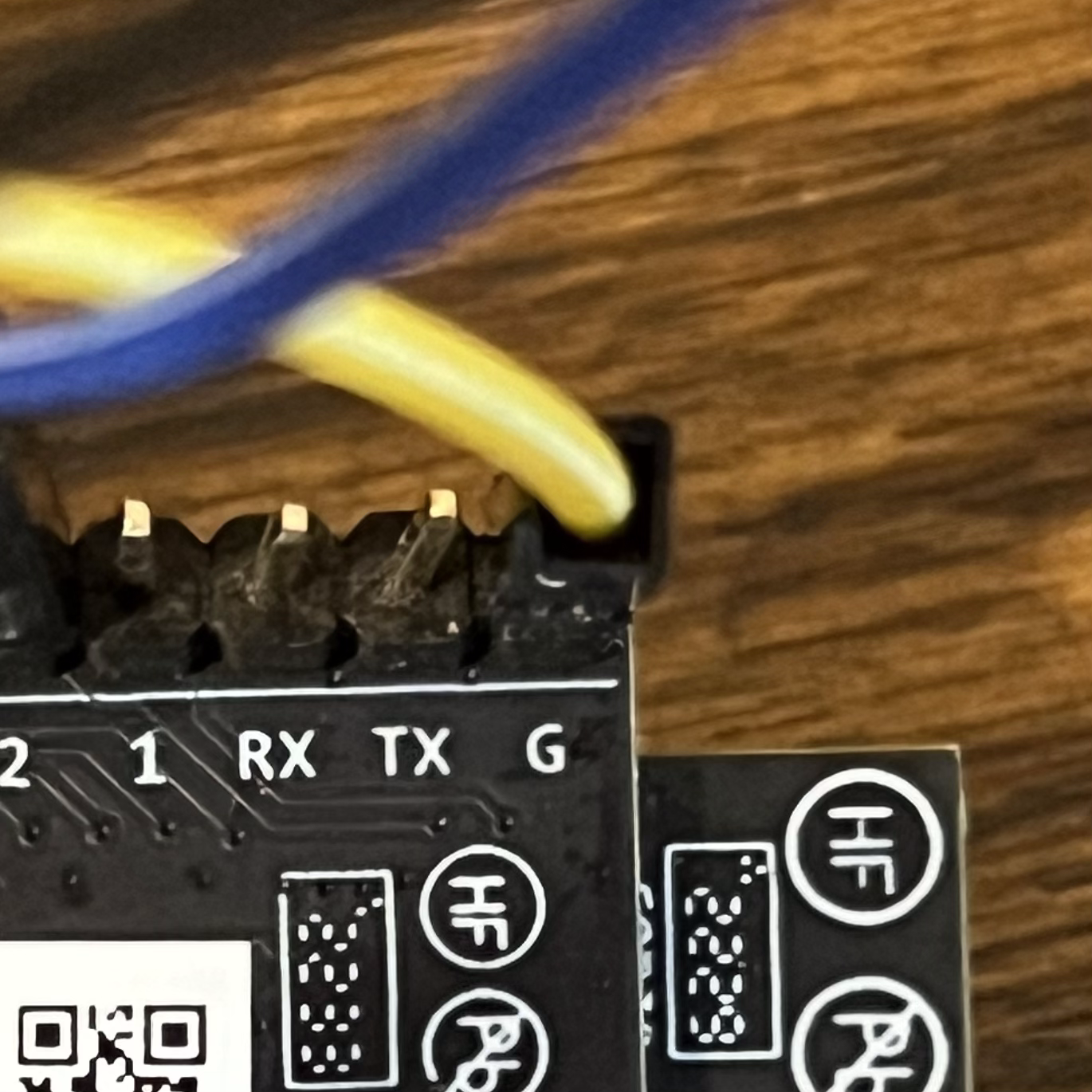
Fig 7. Ground pin on Arduino
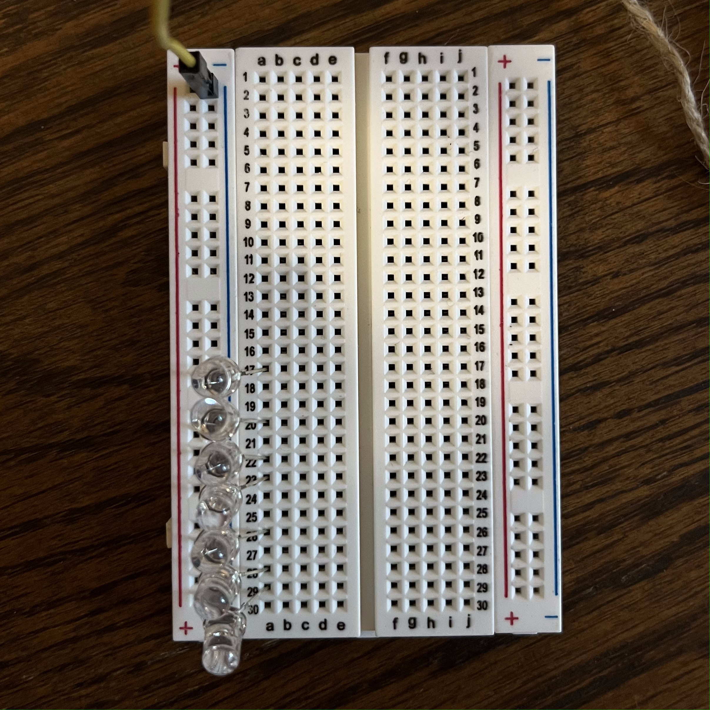
Fig 6. Ground wiring to breadboard
Next, I added the output pins to each of the LEDs and programmed the Arduino to make them blink. This is a variation of the sample code that Arduino provides. After making some modifications to it, this was my circuit and code.
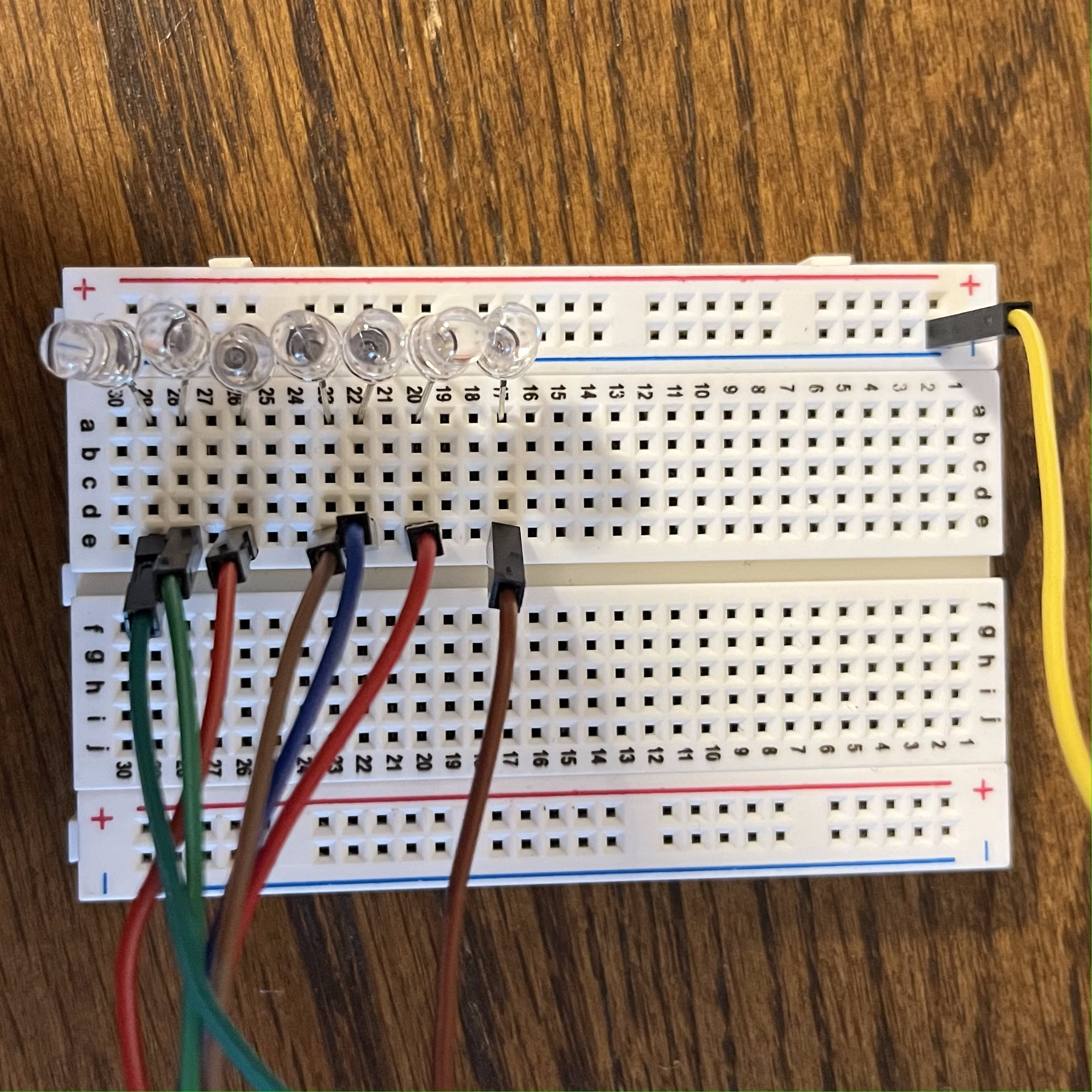
Fig 8. Wiring to the anodes of the LEDs
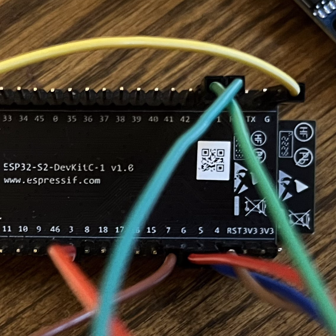
Fig 9. Wiring layout on Arduino
Code:
                void setup() {
                    pinMode(1, OUTPUT);
                    pinMode(2, OUTPUT);
                    pinMode(3, OUTPUT);
                    pinMode(4, OUTPUT);
                    pinMode(5, OUTPUT);
                    pinMode(6, OUTPUT);
                    pinMode(7, OUTPUT);
                }


                void loop() {
                    for(int i = 1; i<=7; i++){
                        digitalWrite(i, HIGH);
                    }
                    delay(1000);
                    for(int i = 1; i<=7; i++){
                        digitalWrite(i, LOW);
                    }
                    delay(1000);
                }
And this was how it worked!
Fig 10. Blinking LEDs
I then modified the code to create half of the wave pattern I was looking for. This was also my first time making use of functions besides the required setup() and loop() functions. This was the function I created and the modified loop() function.
Code:
                void loop() {
                    wave();
                }


                void wave() {
                    for(int i = 1; i<=7; i++){
                        digitalWrite(i, HIGH);
                        digitalWrite((i%7)+1, LOW);
                        delay(80);
                    }
                }
And now it does this!
Fig 11. Half-wave pattern
I wanted to add an additional element to my project, and started messing around with some of the input options on the Arduino. During this process I discovered that the Arduino is very sensitive to voltage input.
Because of this I was able to make the program only run when I was touching the Arduino, effectively using my body as the conductor. Here is the new circuit and modified code.
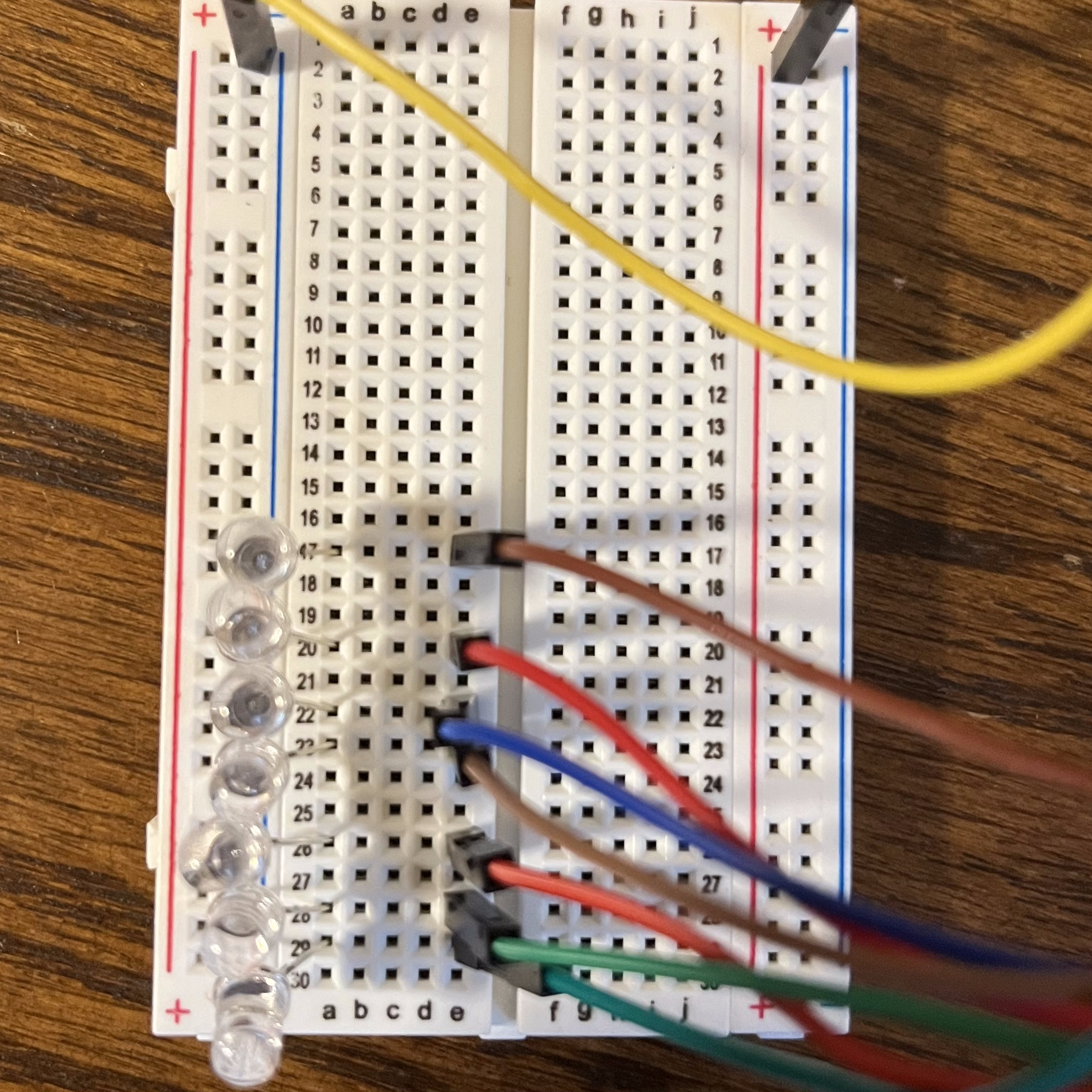
Fig 12. Positive wiring to be used with input
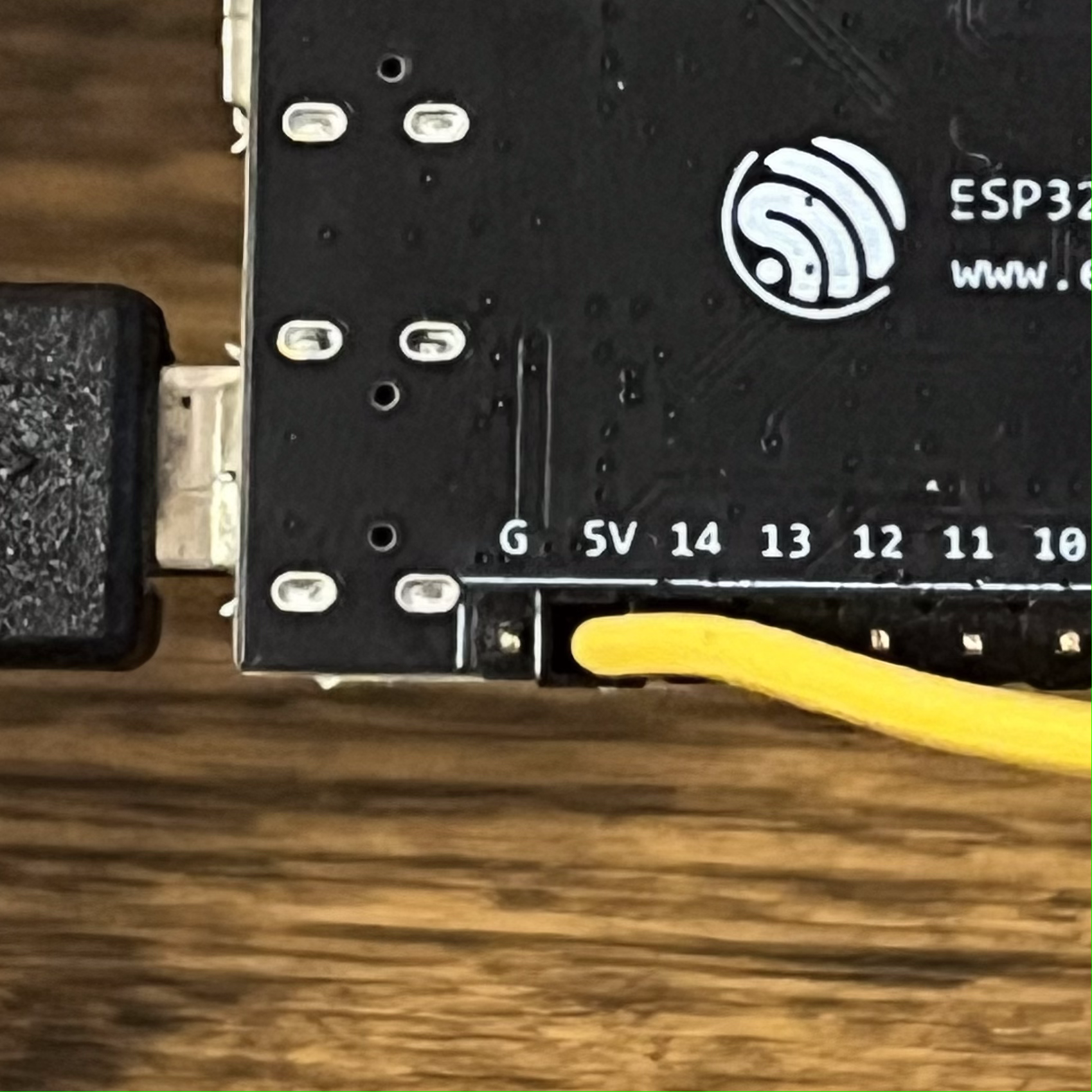
Fig 14. 5v pin on Arduino
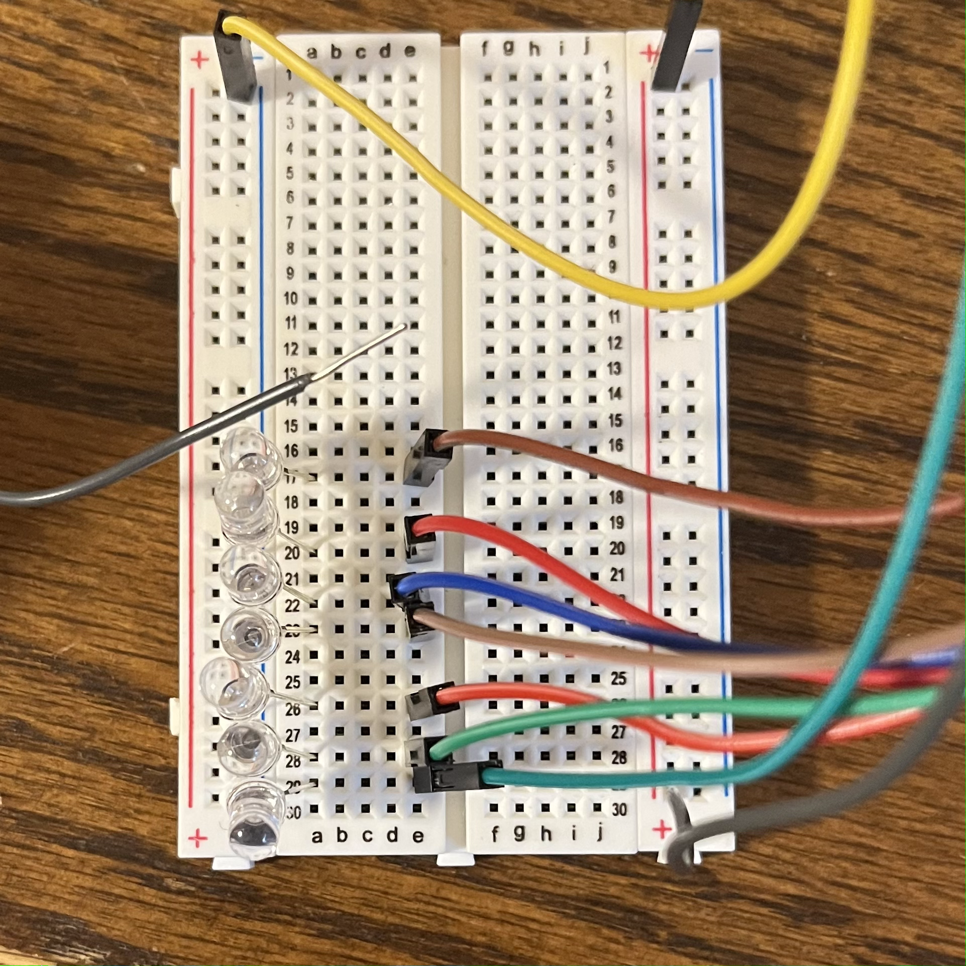
Fig 13. Grey wire to run current through me
Code:
                void setup() {

                    ...

                    pinMode(21, INPUT);
                }

                void loop() {
                    wave();
                    reversewave();
                }

                void reversewave() {
                    for(int i = 1; i<=7; i++){
                      while(digitalRead(21) == LOW){}
                      digitalWrite(i, LOW);
                      digitalWrite((i%7)+1, HIGH);
                      delay(80);
                    }
                }
And this is the final product!
Fig 15. Final Arduino project
Part 2 - Circuit Diagram
In the past, I have used a circuit design software called "EasyEDA" because it has a partnership with a PCB milling firm. I used this software today to model the circuit that I used in my final design.
To start, I opened the "Library" tab and selected the ESP32-S2 board.

Fig 16. EasyEDA's Library tab
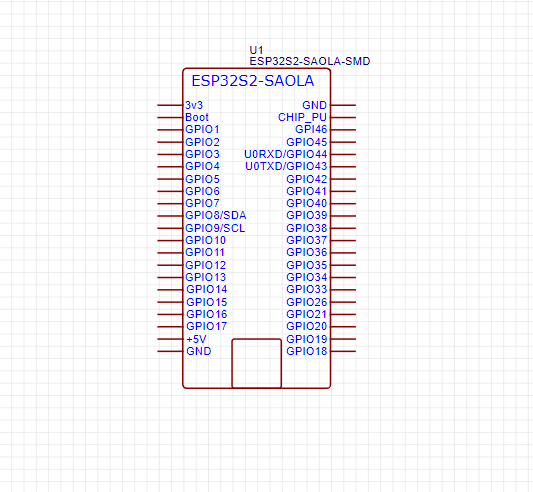
Fig 17. ESP32-S2 layout
Next, I went back to the "Commonly Library" tab and selected 7 LEDs.

Fig 18. EasyEDA's Commonly Library tab
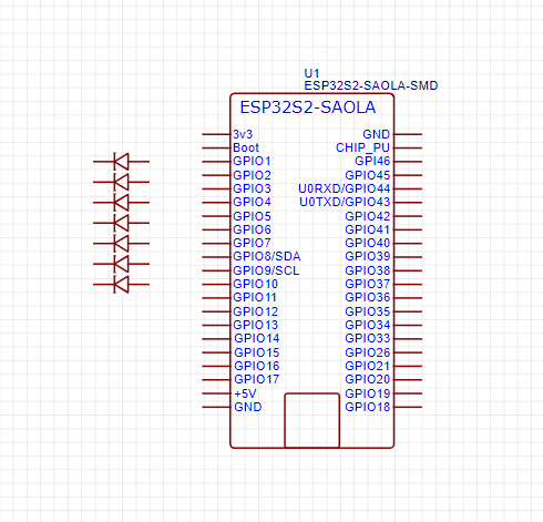
Fig 19. LEDs laid out
I then added wiring from the output pins of the Arduino the anodes of the LEDs.
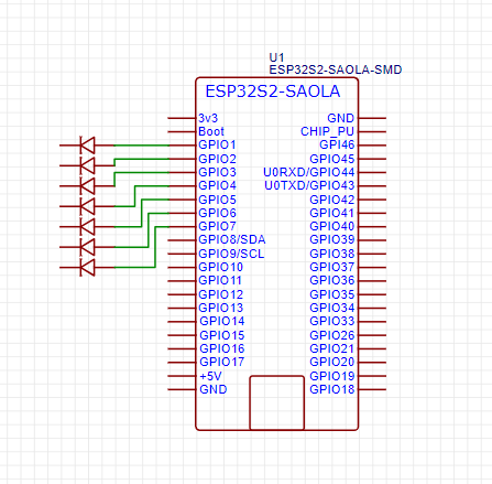
Fig 20. Wiring from Arduino to LEDs
Finally, I added ground to the cathodes of the LEDs and wired up the input pin, using a button to represent my hand touching the Arduino.
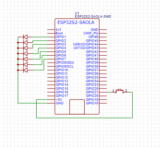
Fig 21. Final schematic
Concluding Remarks
This project made me really familiar with the previously foreign Arduino. I was able to accomplish everything I set out to accomplish, without having to scale back parts of my original plan. Because the Arduino is going to play such a large role in the production of my final project, I'm glad I was able to build a solid foundation quickly. I have already begun experimenting with the MPU6050 chip, and I am excited to see where my project goes!
Files Mentioned in this Document
Wave Code (.INO)