Introduction
Today we were challenged to create a kinetic sculpture that uses circuitry to move. By the end of this lesson we were supposed to know how to power simple circuits, how to use tools to cut wood and other materials, and how to drill and tap a hole.
I remember the first time that I saw a wave pool and how fascinated I was with them. Using vibrations and barriers, these pools can generate different patterns of waves that behave differently. I wanted to emulate this phenomenon using sawdust as my particulate matter, and an eccentric motor to generate the vibrations that I needed.

Fig 1. Wave pool render
Components
This project required 3 components: the box to hold the sawdust, the sawdust, and the apparatus to shake the box.
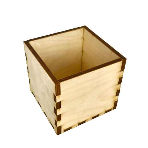
Fig 2. 3D Press-fit box
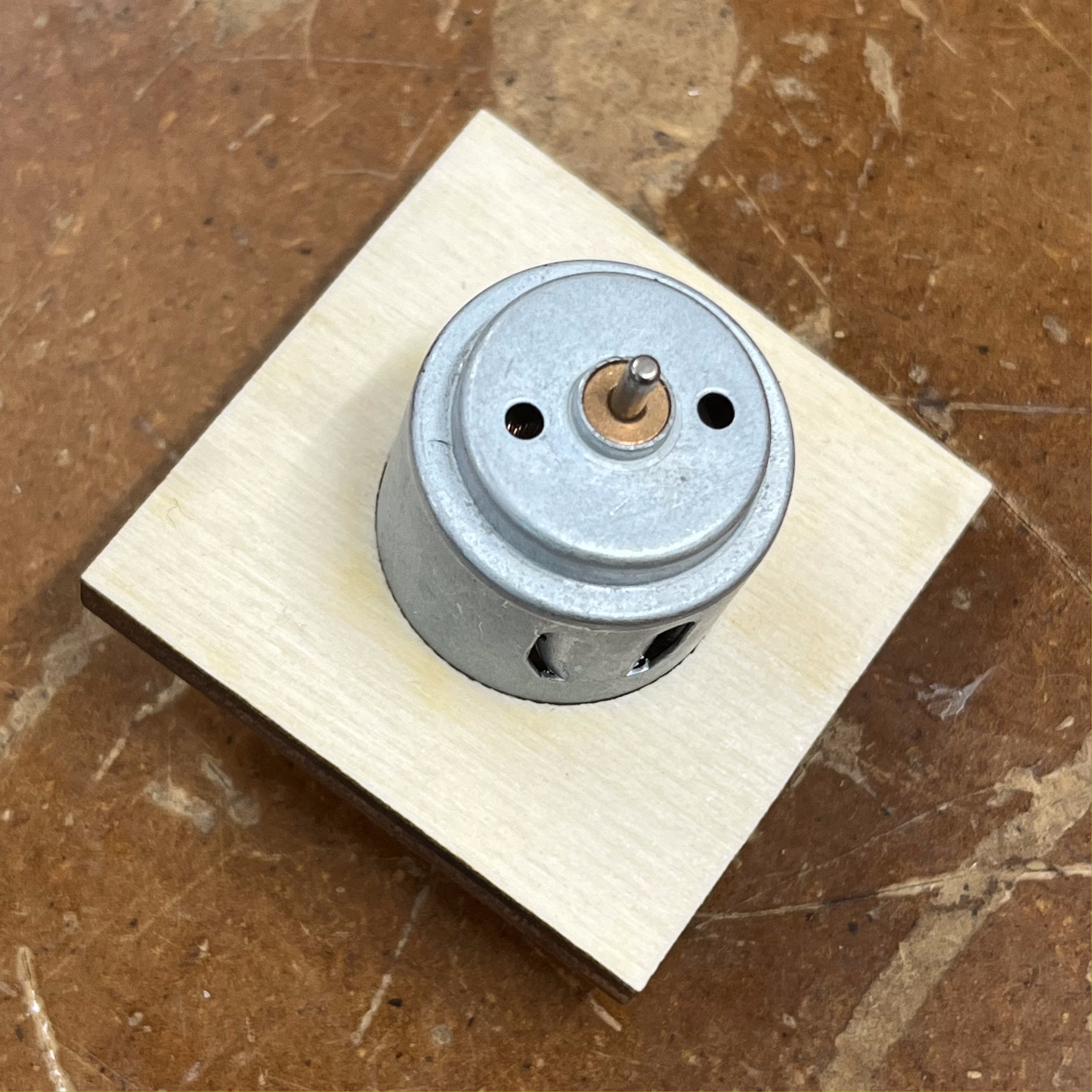
Fig 4. Motor held in place by motor holder
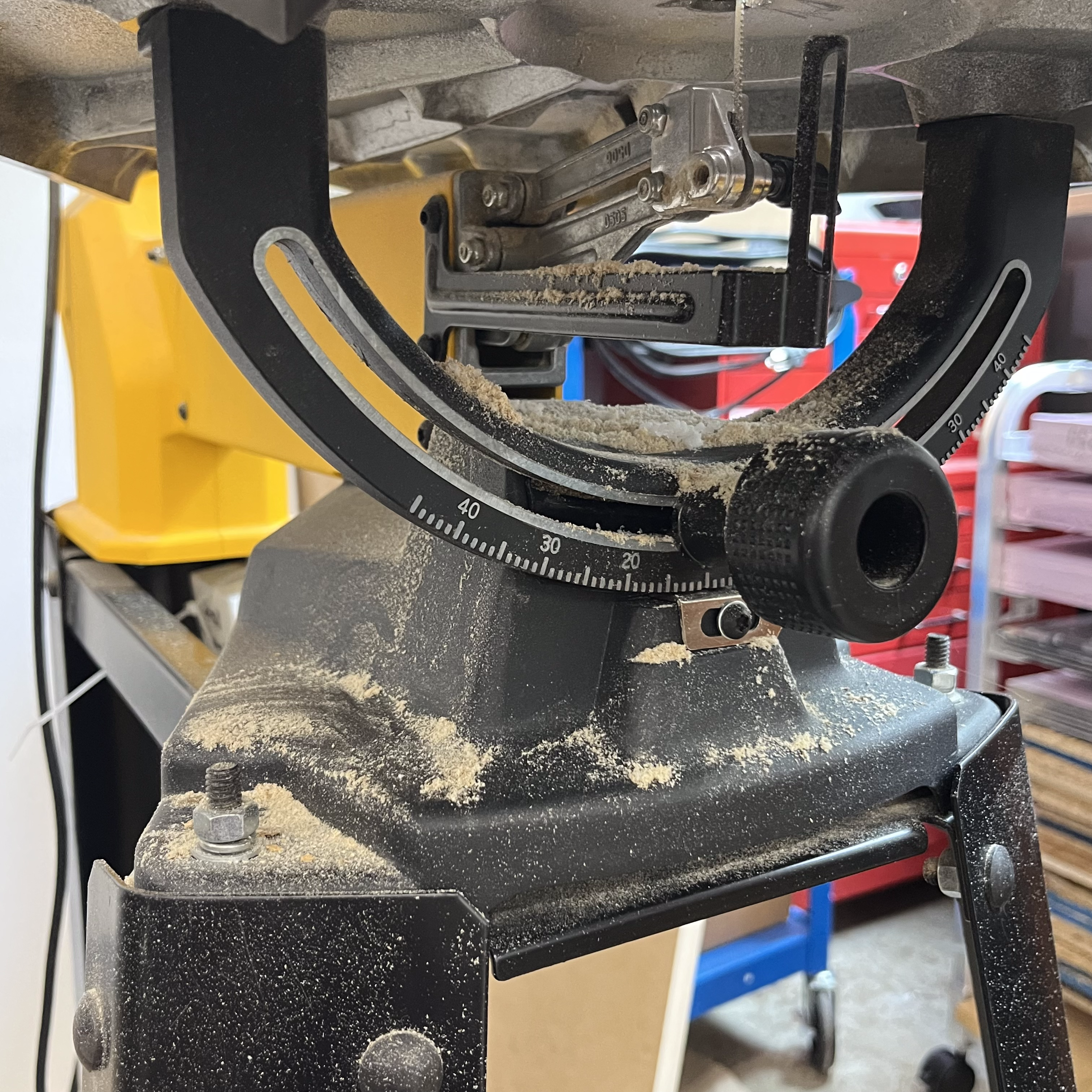
Fig 3. Bandsaw covered in sawdust
In Figures 1, 2, and 3, I display the the 3 main components used in my kinetic sculpture.
Part 1 - Box press-fit construction
In order to make the "wave pool" sculpture, I needed to create a container to hold the dust and the vibrating apparatus. It was important that this container was held together tight enough so that the dust did not leak out, and that the material was rigid enough to not deform with the vibrations. For these reason, I decided a press-fit box out of wood would not only satisfy these conditions, but was something I was able to make.
To start, I used a software that Bobby recommended: MakerCase. This software created the schematic for a press-fit box, accounting for size, material width, and kerf. After measuring my material and inputting these values into the software, I had my schematic to cut.
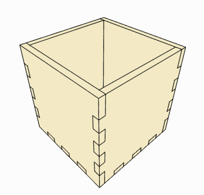
Fig 5. MakerCase's render of the box
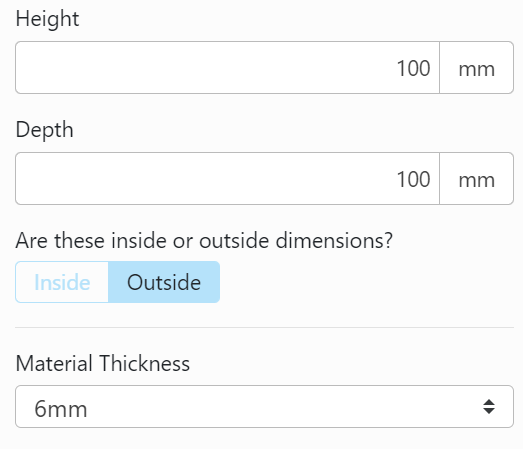
Fig 6. Layout of some settings
I then exported the schematic as a "dxf" file and edited it in Inkscape. After giving all of the lines 0.001 thickness and red coloration (settings for cut), I ran the design on the laser cutter.
Part 2 - Vibration apparatus
In class we were introduced to a variety of motors, including an eccentric motor. As I have never worked with an eccentric motor before, I decided I was going to use this in my project. In order to mechanically attatch this motor to the box designed in Step 1, I had to create a custom piece of hardware.
First, I measured the diameter of the motor that I was going to use. I then used Fusion360 to create a basic square with a hole in the center for the motor.
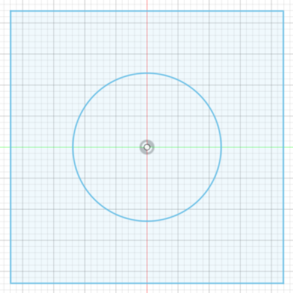
Fig 7. 2D sketch of motor holder
After editing this design in Inkscape and cutting it I tested it with a motor. Sure enough, it fit perfectly!
Fig 8. Motor held in place by motor holder
Anticipating that the motor might still fall out when it starts to vibrate, I added rubber cement to the holder to provide resistance to this.
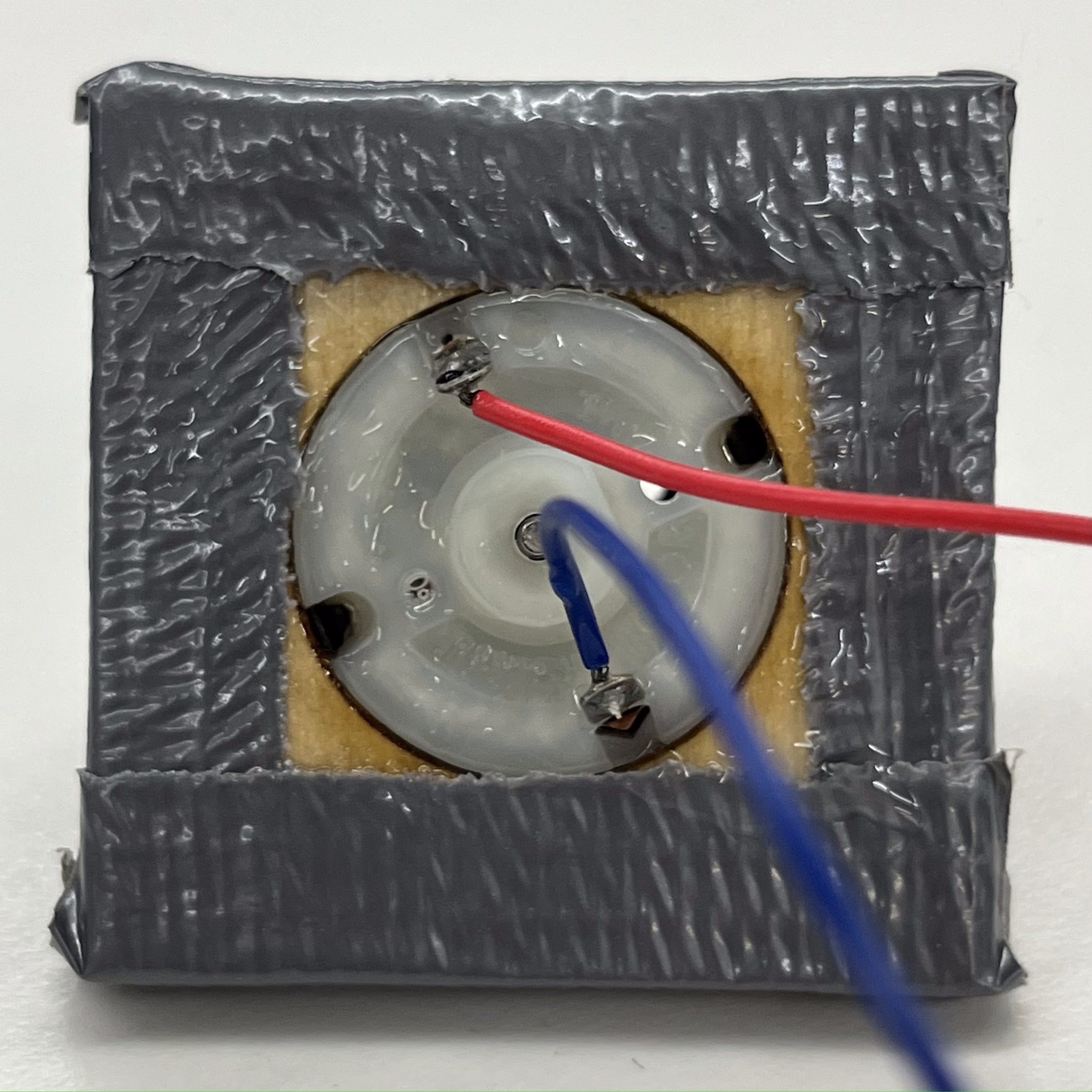
Fig 9. Rubber cement application
After this, I drilled and tapped holes into both the box and the motor holder to hold them together.
Important: In order to drill into the box, I had to drill into the plies. If I did not go slowly, the wood would splinter. Additionally, it was critical that I had the wood perfectly vertical.
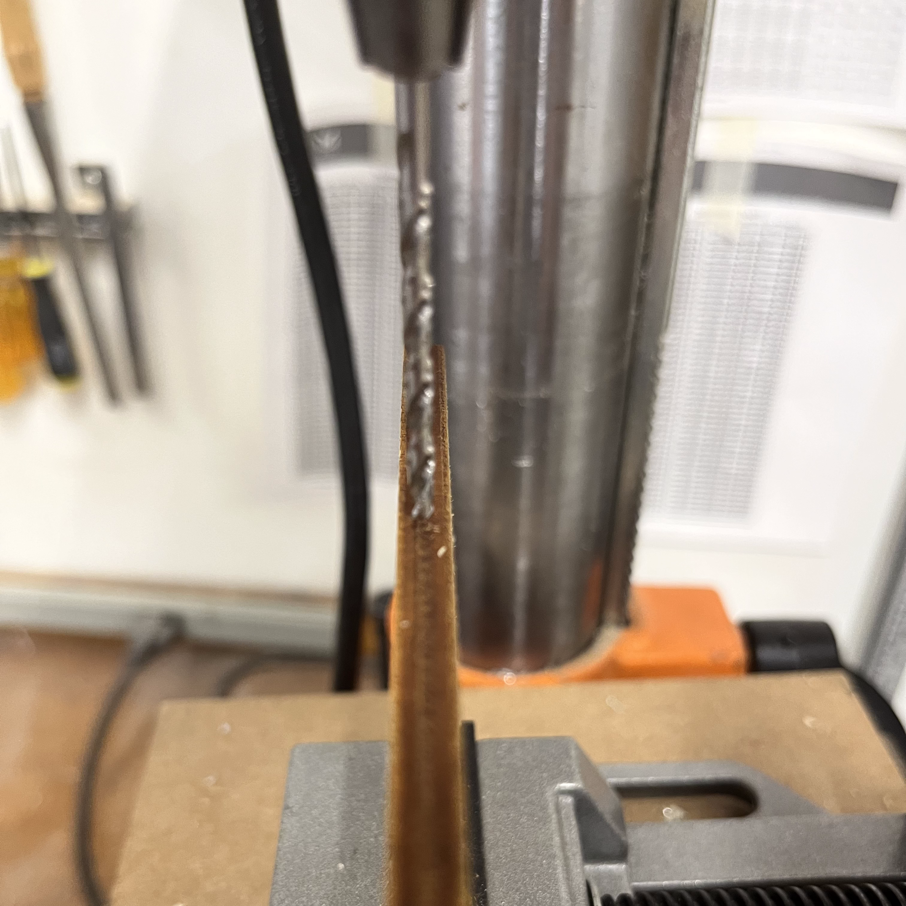
Fig 10. Drill press and setup
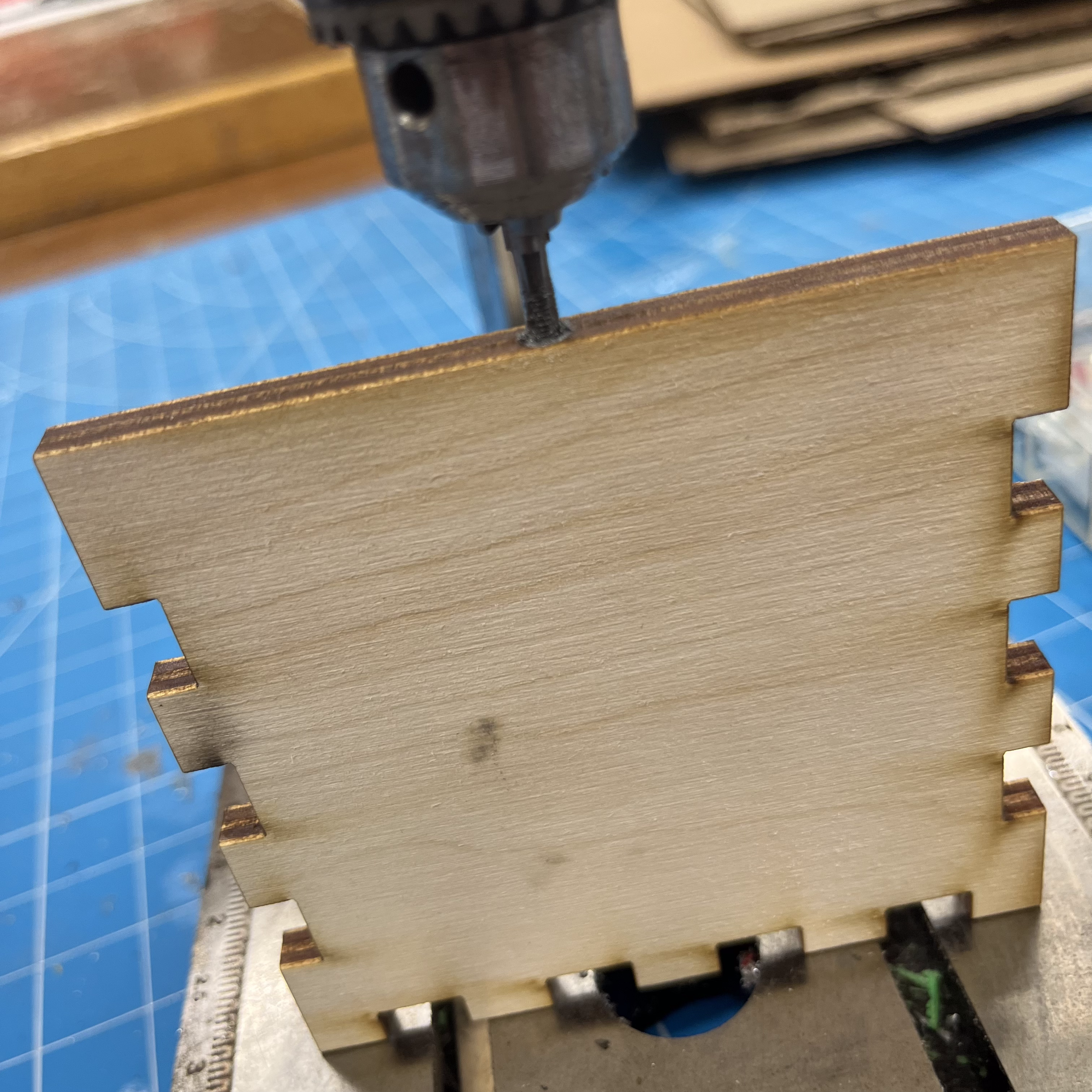
Fig 11. Tapping a hole into the plies
After performing the same steps on the motor holder, I screwed these parts together. Unfortunately, the M3x20 screws were the only available screws that could go through both pieces. To accommodate this restriction, I had to redo the drilling and tapping for deeper holes.
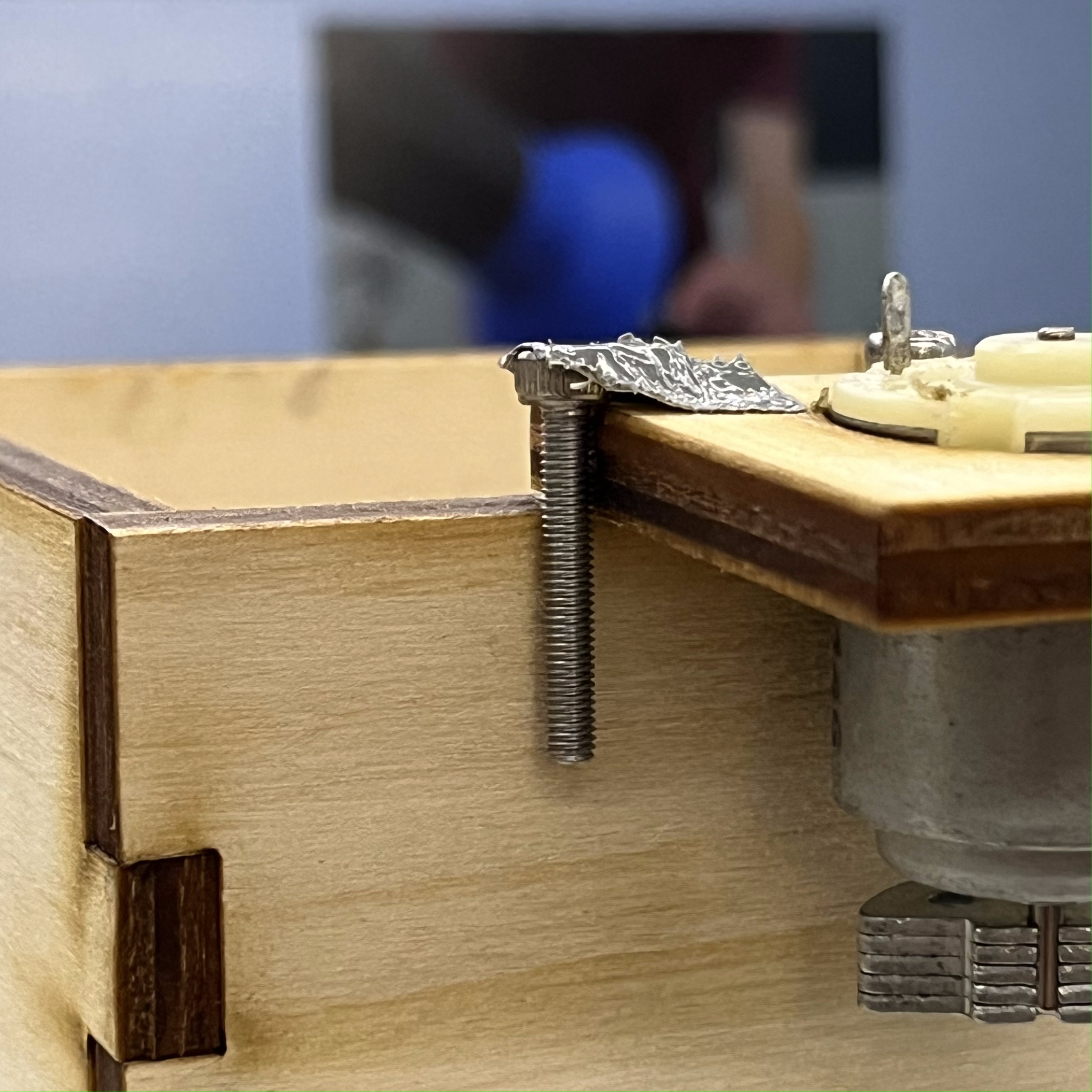
Fig 12. Depth of screw penetration
I then grabbed the eccentric motor and soldered leads onto it.
Fig 13. Soldering leads
Important: I used much more solder than I likely needed to. I was afraid that the leads would snap off as the sculpture vibrated.
I then tested my sculpture, and was met with an unexpected problem: the vibrations were causing the screws to unscrew themselves. I added some extra rubber cement to help alleviate the shock from the vibrations, which seemed to work.
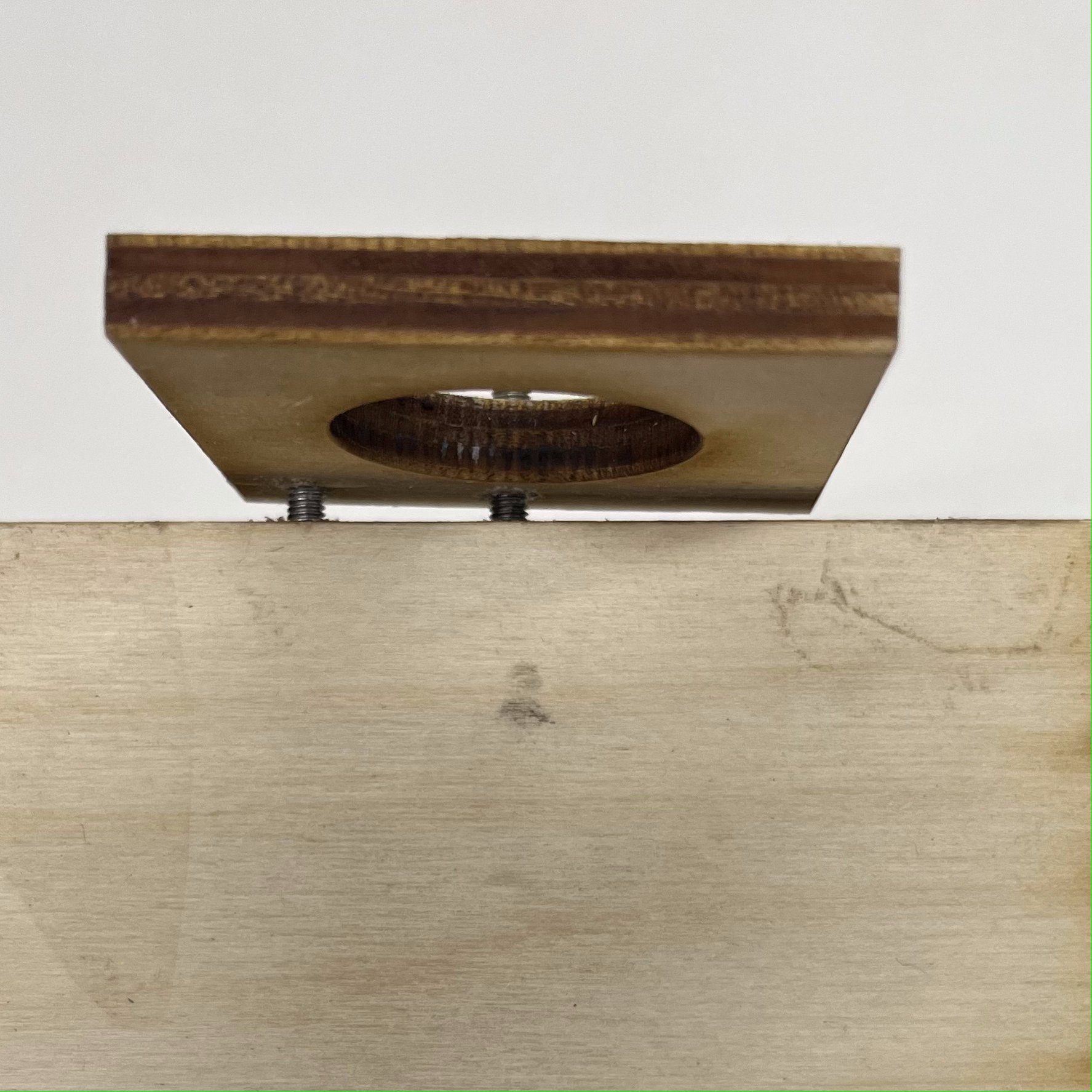
Fig 14. Loosened screws
Reduce, Reuse, Recycle!
Now that my box was able to vibrate, I needed a way to get the sawdust I needed to fill it. For this, I turned to the band saw, which was absolutely covered in sawdust.
Fig 15. Bandsaw covered in sawdust
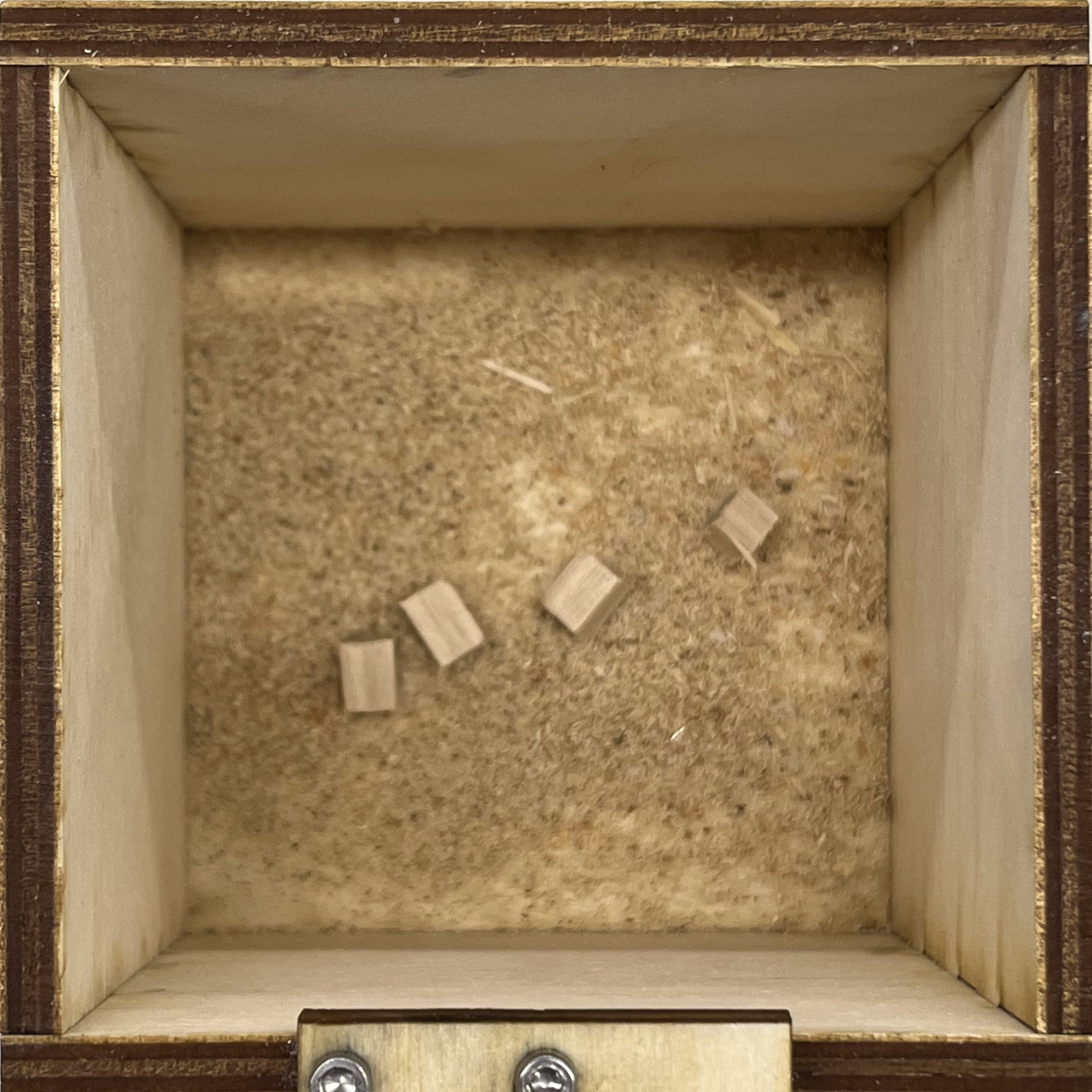
Fig 16. Sawdust inside kinetic sculpture
After collecting the sawdust from the band saw, I now had to find the optimal voltage and current to run my circuit with. For this, I used the benchtop power supply and modulated it until I got the amount of vibration I was looking for (6v). Then, by measuring the resistance of the motor, I could determine the amount of current it was using with Ohm's Law.
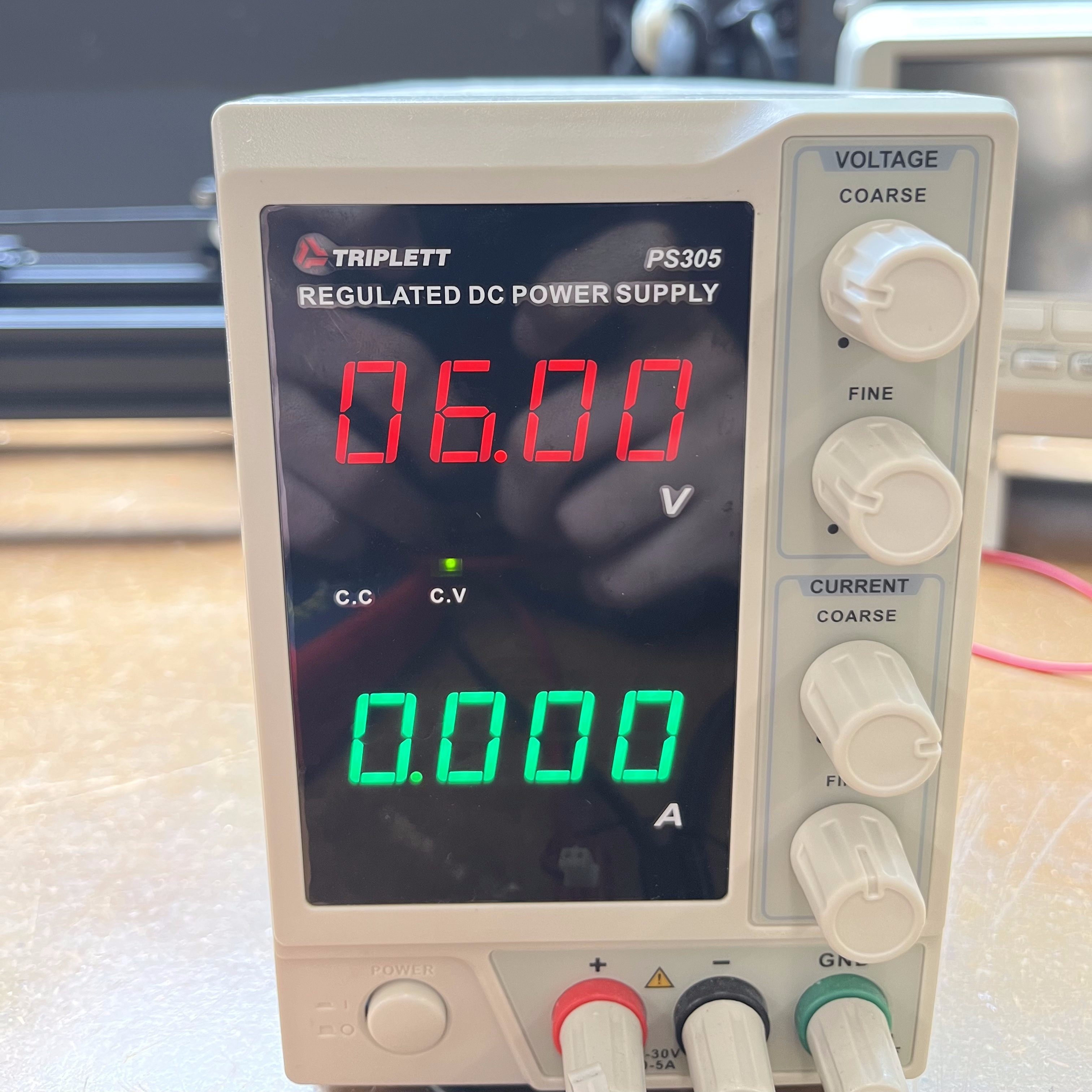
Fig 17. Benchtop power supply
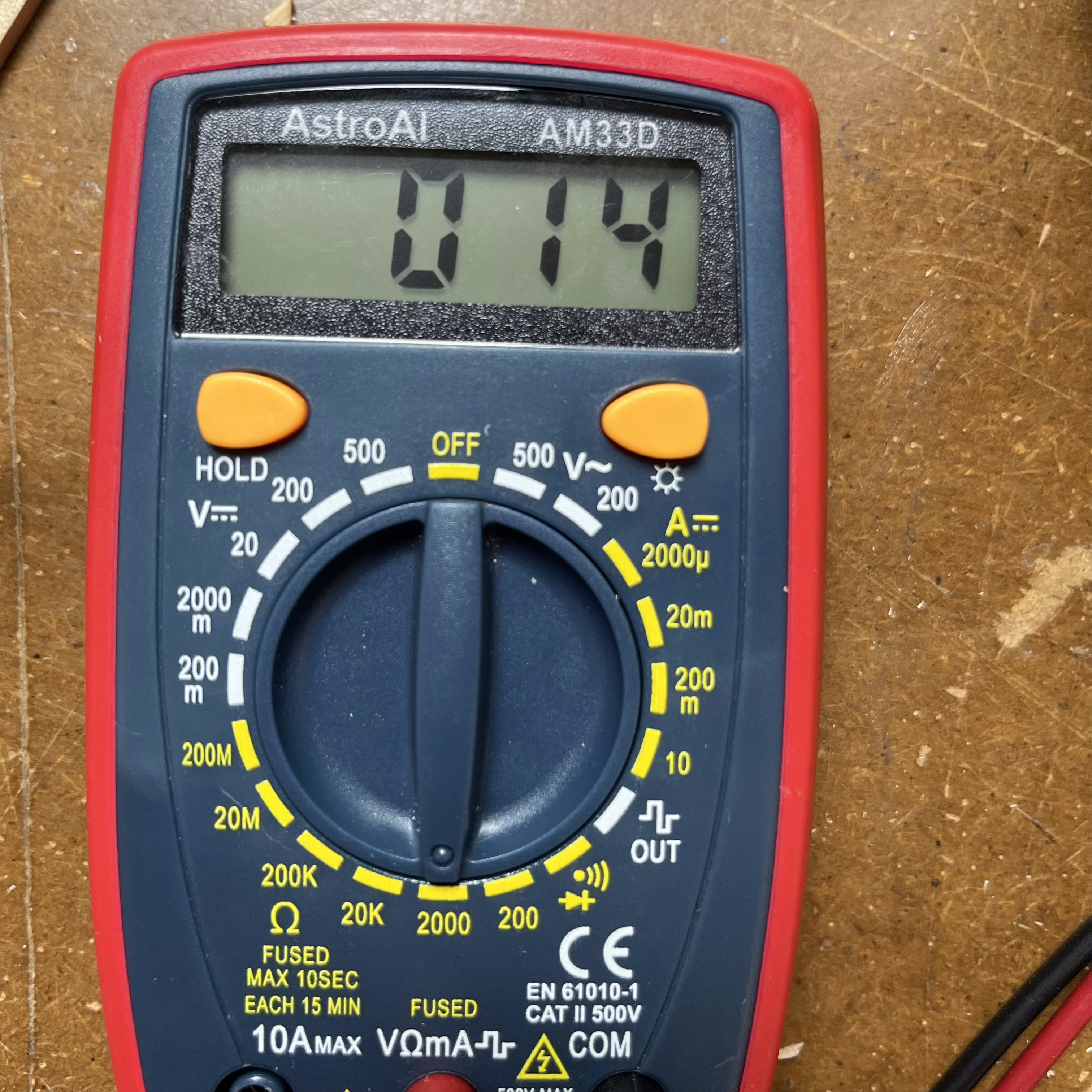
Fig 18. Multimeter measuring resistance
Because the circuit used 6 volts and the motor had a resistance of 14 ohms, the amount of current it was using is around 429mA.
Finally, I had finished my kinetic sculpture!
Fig 19. Final kinetic sculpture
Concluding Remarks
This project was a great way to familiarize myself with the eccentric motor, which, prior to this class, I had never used before. I also learned a lot about how to mechanically attatch pieces of of a larger project, which will undoubtedly come up many more times in this class and my future engineering projects. I definitely think that my solution was not the best one, and I would love to spend time seeing if there are other simple ways of mechanically attatching pieces like these together.
Files Mentioned in this Document
Motor Holder (.DXF)
Box (.DXF)