Introduction
Today we were challenged two do 2 things: create a press-fit construction kit that can be assembled multiple ways and measure and model two household objects in CAD. By the end of this lesson we were supposed to know how to use calipers to measure objects, how to operate the laser cutting machine, and how to proficiently use CAD (I chose Fusion360).
Growing up, I have always loved playing with LEGOs and decided to use them as inspiration for my project. Additionally, I decided to pick one simple object to model (to become comfortable with this type of digital modeling) and one difficult object to model (to challenge myself and develop skills in digital modeling).
Components
These projects required 3 components: the "LEGO" to be laser cut as well as the roll of tape and glue bottle to model.
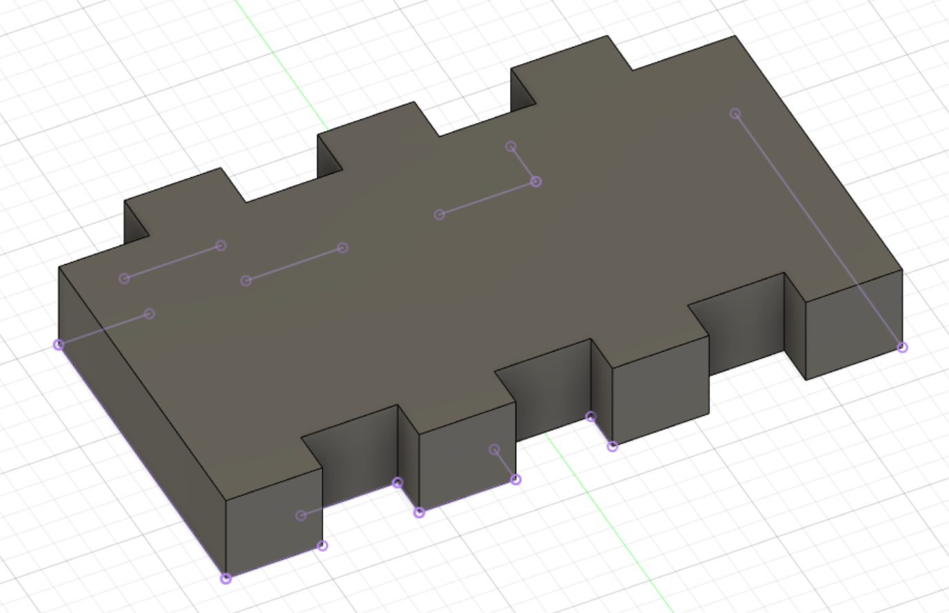
Fig 1. 3D Render of "LEGO" Design
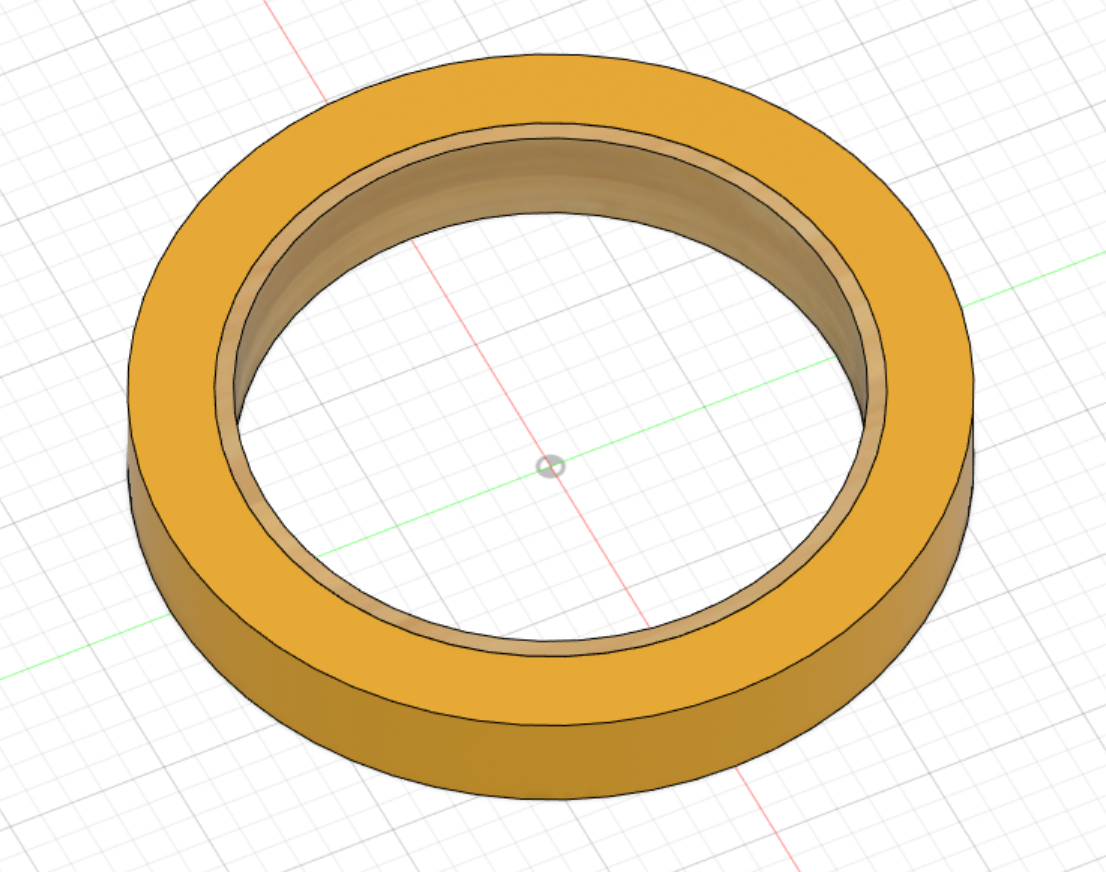
Fig 3. 3D Render of Roll of Tape
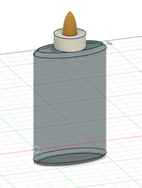
Fig 2. 3D Render of Glue Bottle
In Figures 1, 2, and 3, I display the 3D models of the "LEGO", Roll of Tape, and Glue Bottle, respectively. It should be noted that these figures are all to scale (although the "LEGO is slightly distorted to account for kerf).
Part 1 - "LEGO" press-fit construction kit
In order to truly make a LEGO-style press-fit construction kit, I needed to capture the two axis with which one can connect LEGO pieces. This required that the pieces have indentations and extrusions exactly the width of the cardboard (or other material) used to fabricate them. I began by measuring the cardboard with calipers (Figure 4), and determined that this constant was 3.9mm.
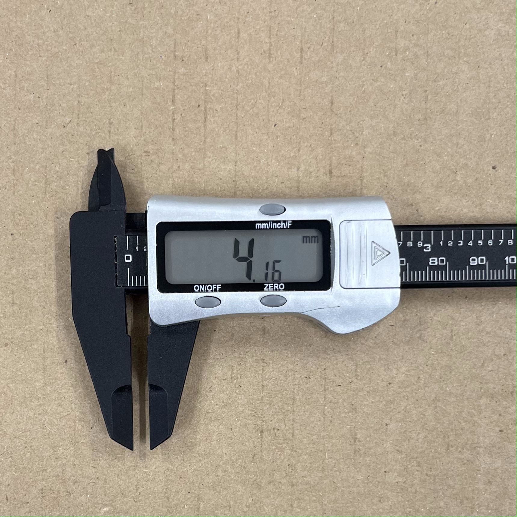
Fig 4. Calipers after measuring cardboard*
*This is a measurement of a separate piece of cardboard. The 3.9mm constant was determined a priori.
Next, I had to model the shape I wanted in Fusion360. This was accomplished using four main tools that I will refer to later: the "two-point rectangle", "rectangular pattern", "sketch dimension", and "move to point" tools. These tools were mostly simple, although the rectangular pattern tool had properties that made it ideal for modeling an object that might be changed, as I mention below.
To begin, I used the "two-point rectangle" and "sketch dimension" tools to create the "body" of the design as well as the indentations and extrusions.
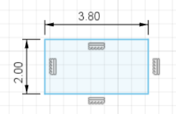
Fig 5. A rectangle to be used as an extrusion
Next, I used the "move to point" tool to align the indentations and extrusions to the body before moving them to the proper locations.
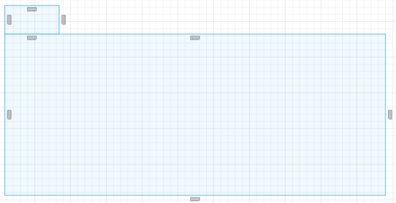
Fig 6. An extrusion and the body after initial movement
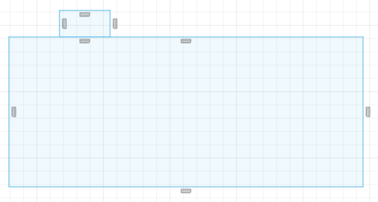
Fig 7. An extrusion and the body after final movement
Then, I used the "rectangular pattern" tool to evenly distribute multiple copies of the indentations and extrusions across the body and removed redundant edges.
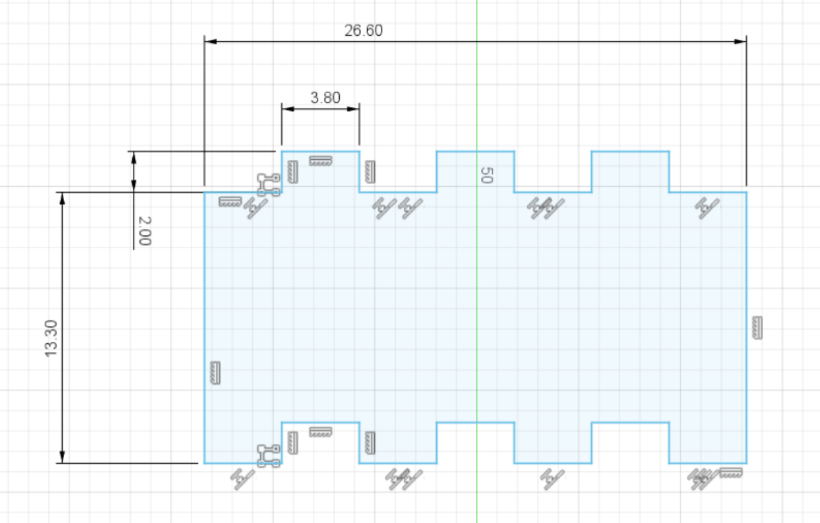
Fig 8. Final sketch of "LEGO" Design
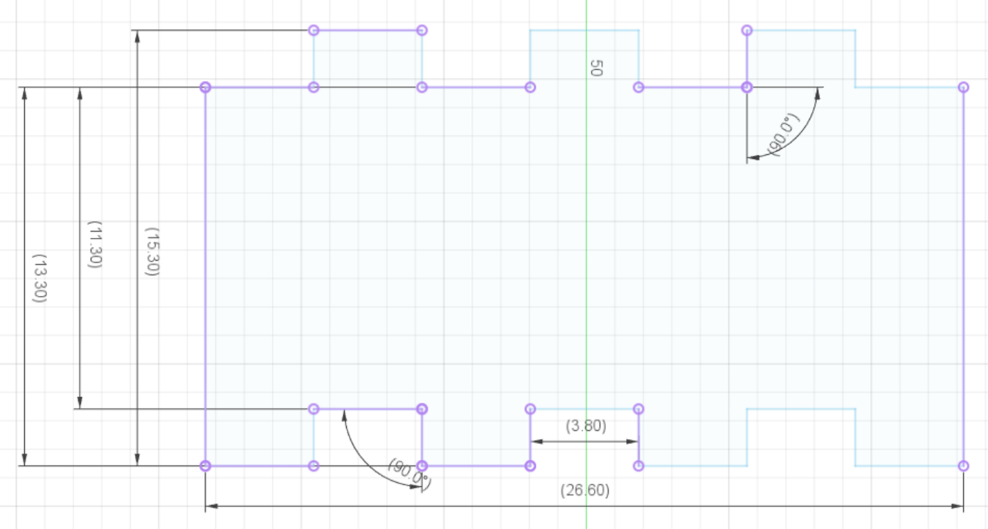
Fig 9. Technical Layout of "LEGO" Design
After modifying the design in "Inkscape", I was left with a PDF with 16 copies of my first design. I neglected to include any engravings (blue), only including the red markings which denote full cuts.
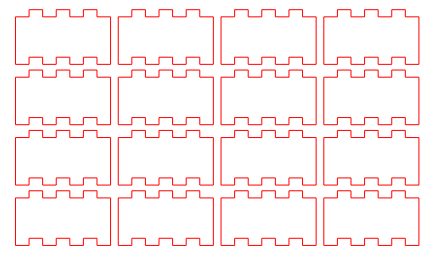
Fig 10. Final PDF of "LEGO" Design
I then imported this PDF into UCP and cut it out on the laser cutter.
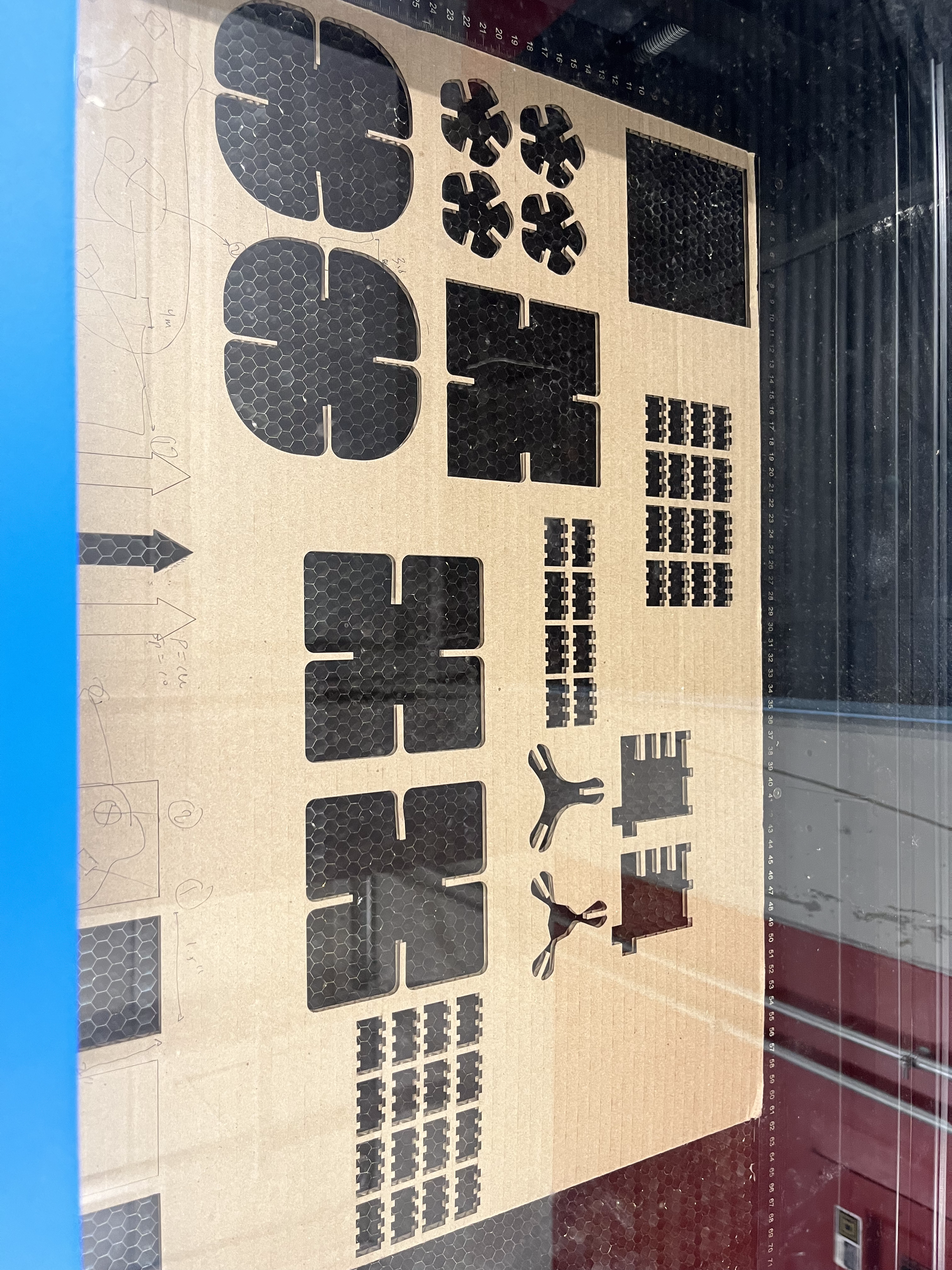
Fig 11. Laser Cutter and cut cardboard
Important: I did not account for enough kerf, and these pieces did not fit together properly.
I redid the design slightly, accounting for a larger amount of kerf, and re-cut my new design. The rectangular pattern I used before turned out to be crucial in redoing this portion as it ensured an even spacing between the copied extrusions and indentation regardless of how large or small they were. This tool will be very useful if I model repetitive objects in the future.
This process was identical to the process explained above, and is omitted from this documentation as it does not add to the significance of my project.
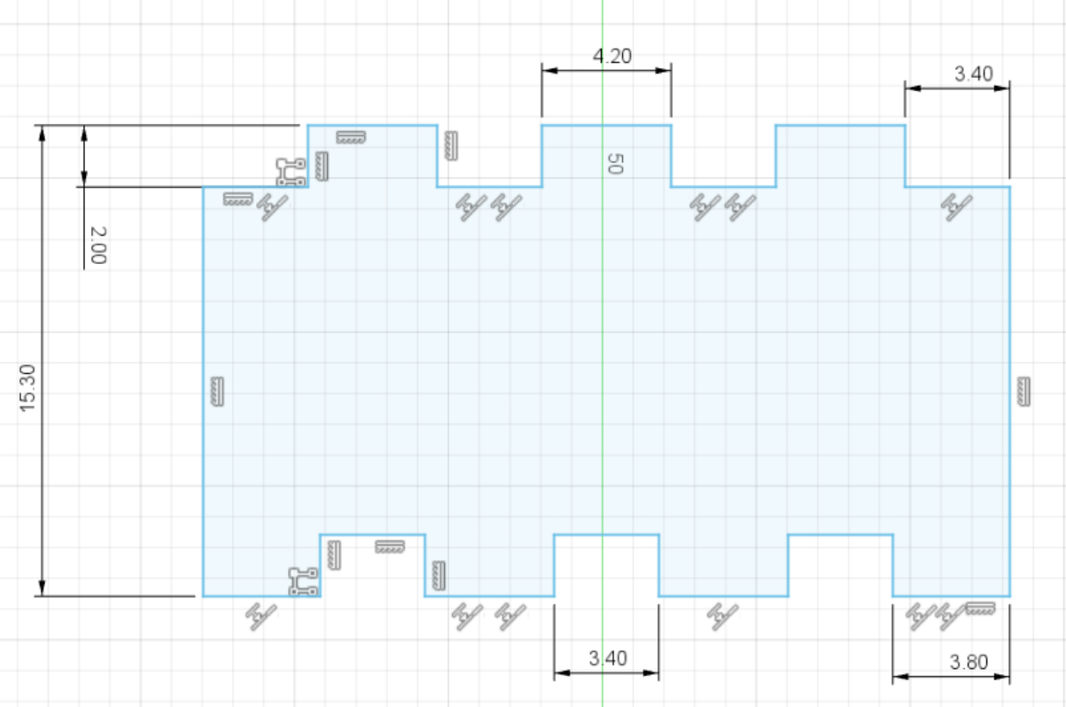
Fig 12. Redone "LEGO" Design
These new pieces fit together perfectly! I could assemble them in many different ways, just like real LEGOs.
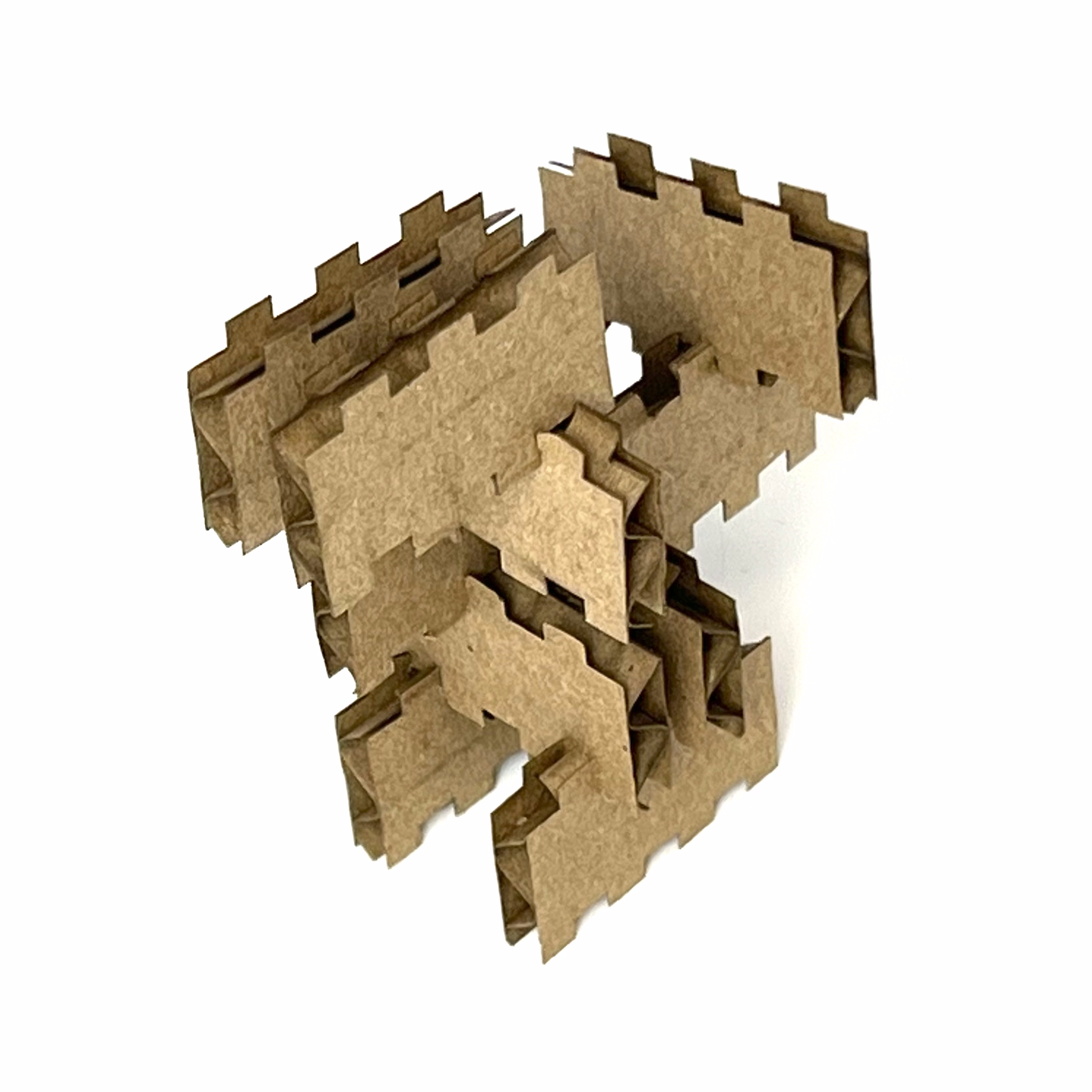
Fig 13. "LEGO" Design Construction
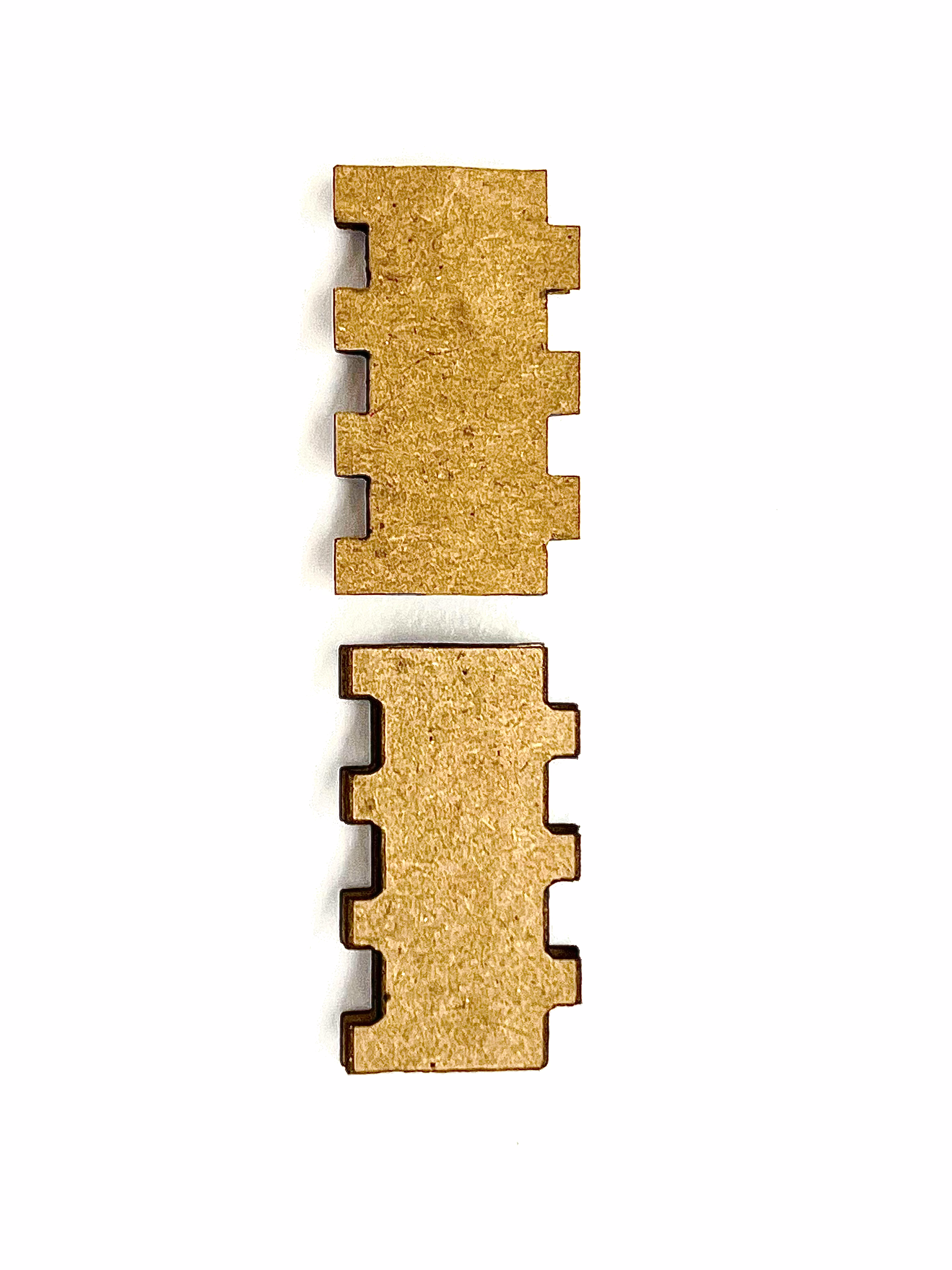
Fig 14. V1 vs V2 Comparison
Part 2 - Preface
Before moving on to modeling objects found around the shop, I followed a simple tutorial to familiarize myself with 3D modeling using Fusion360.
First, the tutorial instructed that I create a simple sketch consisting of a rectangle and two circles.
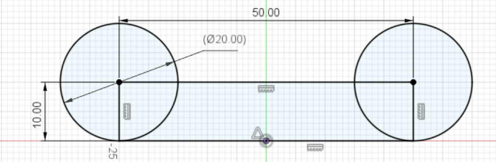
Fig 15. Measured sketch of practice design
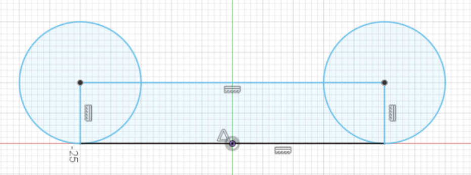
Fig 16. Sketch of practice design
Then, I extruded the sketch to create a 3D body.
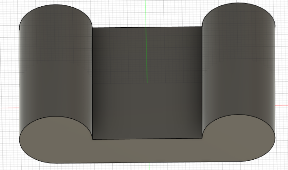
Fig 17. Extruded body of practice design
I then created two holes in my body using the "hole" tool. I also added a fillet to the entire design to finish it.
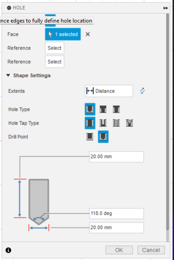
Fig 18. Window used to create holes
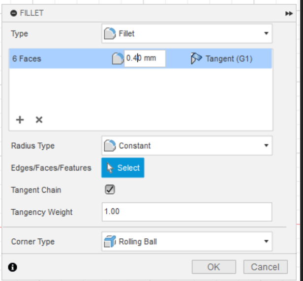
Fig 20. Window used to create fillet
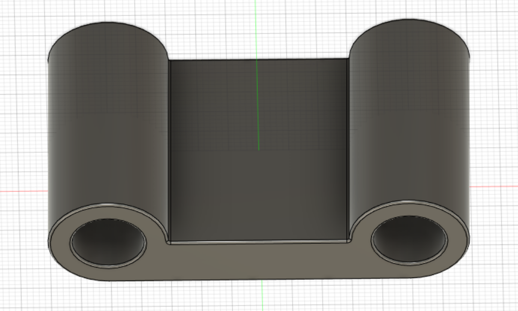
Fig 19. 3D Render of tutorial design
Part 2 - Modeling household objects
For this part of the assignment, I measured and modeled two objects I found in the shop: a roll of tape and a bottle of glue. By measuring these objects using calipers, I can ensure that my model is perfectly to scale (which is useful for aplications such as 3D printing).
Roll of Tape
I wanted to start with a simpler object before moving onto a more complicated one. For this object, I will use its circular nature to my advantage by constructing a cross-section and rotating it around a center point.
First, I began by measuring the roll of tape with a pair of calipers. I determined that the tape had a diameter of 106.5mm, that the cross section is 15.5mm wide, 17.78mm tall, and the inner cardboard is ~2.8mm wide.
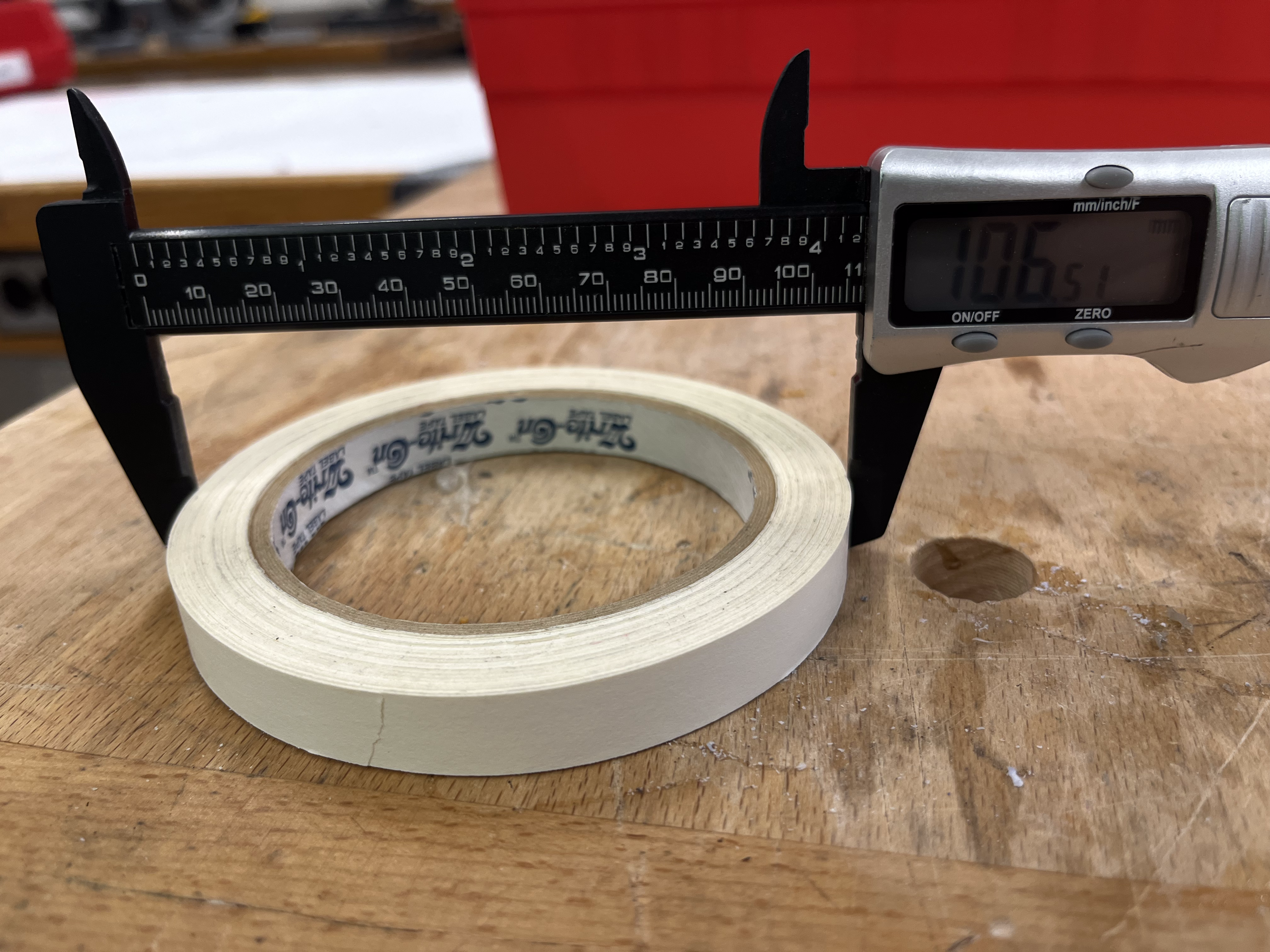
Fig 21. Measuring the tape
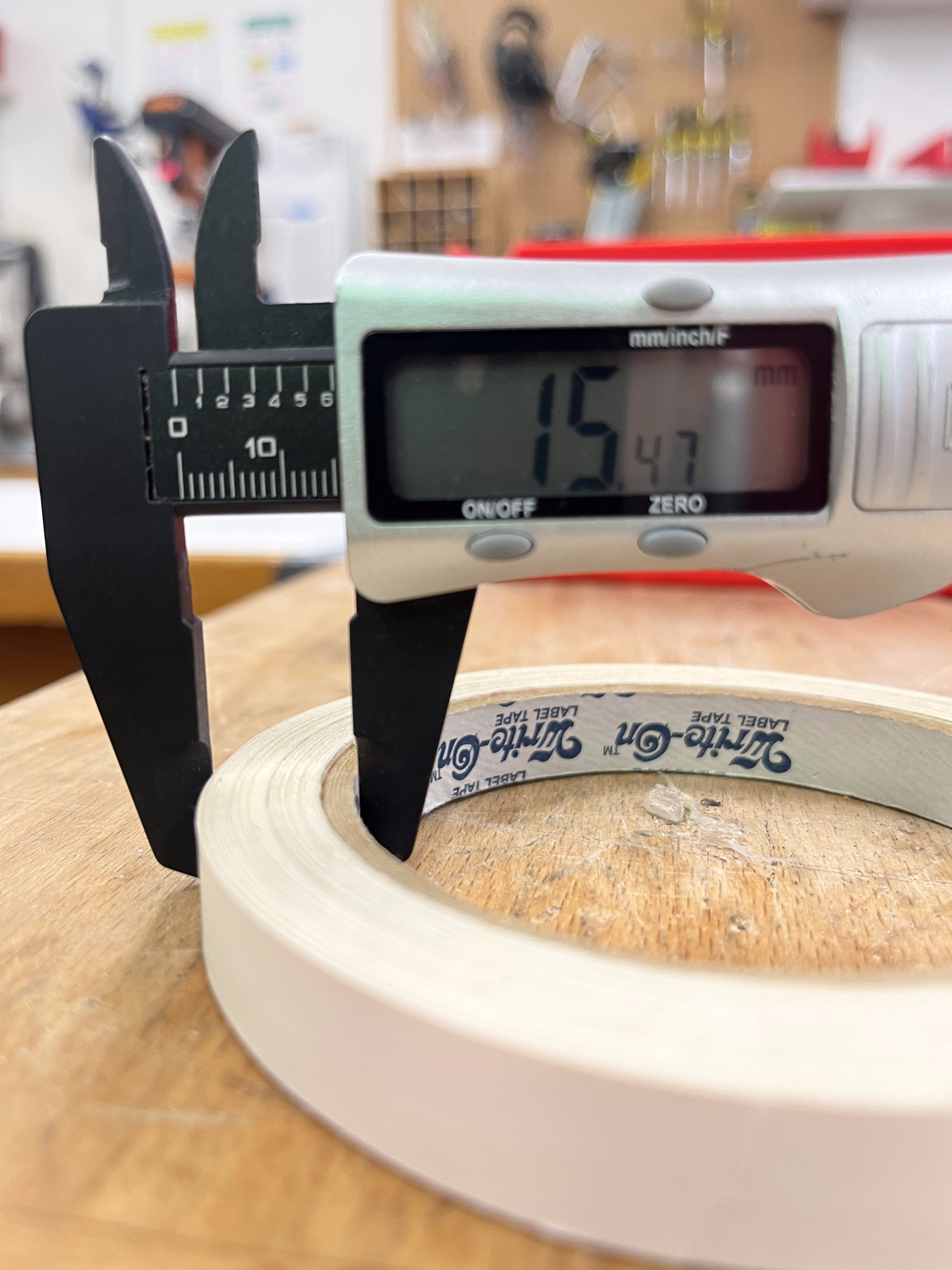
Fig 22. Also Measuring the tape
Next, I went about constructing a cross-section to the parameters mentioned above.
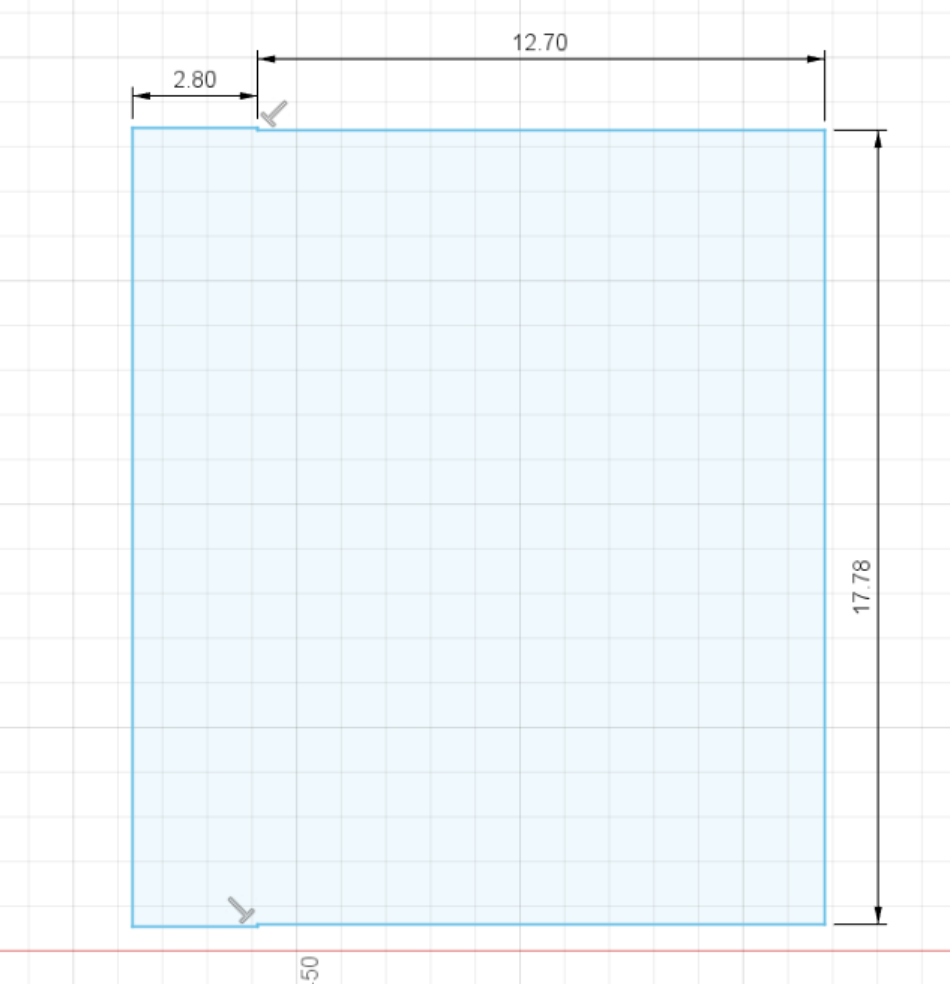
Fig 23. Tape cross-section sketch*
*I decided to add an 0.05mm lip on either end of the sketch to distinguish between cardboard and tape.
Finally, I rotated the cross section such that it had an inner radius of 37.75mm ((106.5/2)-15.5).
Fig 24. Final Roll of Tape render
Bottle of Glue
I then moved on to a more complicated object. The glue bottle contains 3 separate components and a variety of difficult curves.
First, I began by measuring the glue of tape with a pair of calipers. I determined that the body roughly elliptic with a major axis of length 64.61mm and minor axis with length 31.85mm. The body was roughly 100.81mm tall. More dimensions can be found in the file below, but are omitted from this page for not adding to the significance of the project.
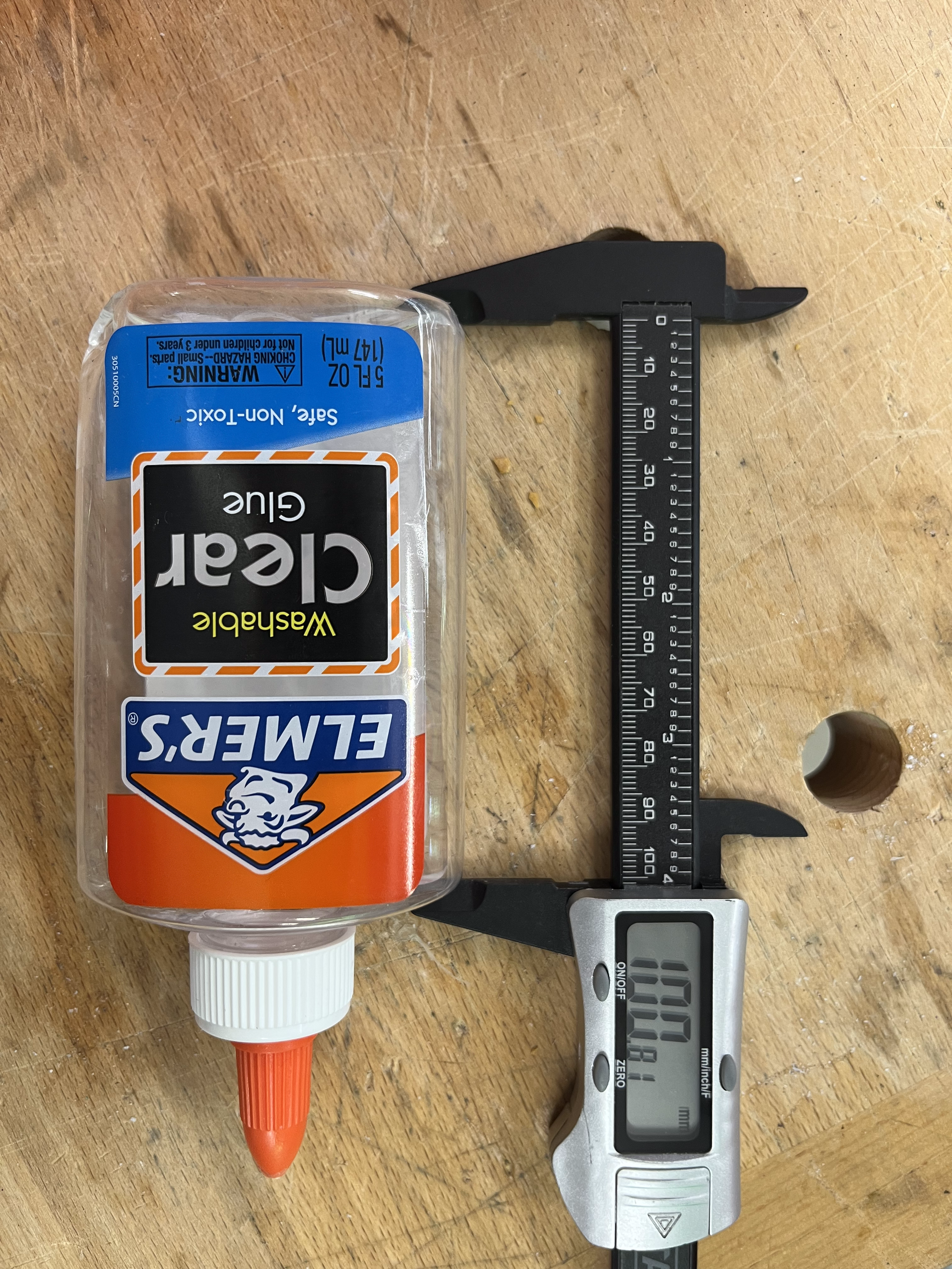
Fig 25. Measuring the bottle of glue
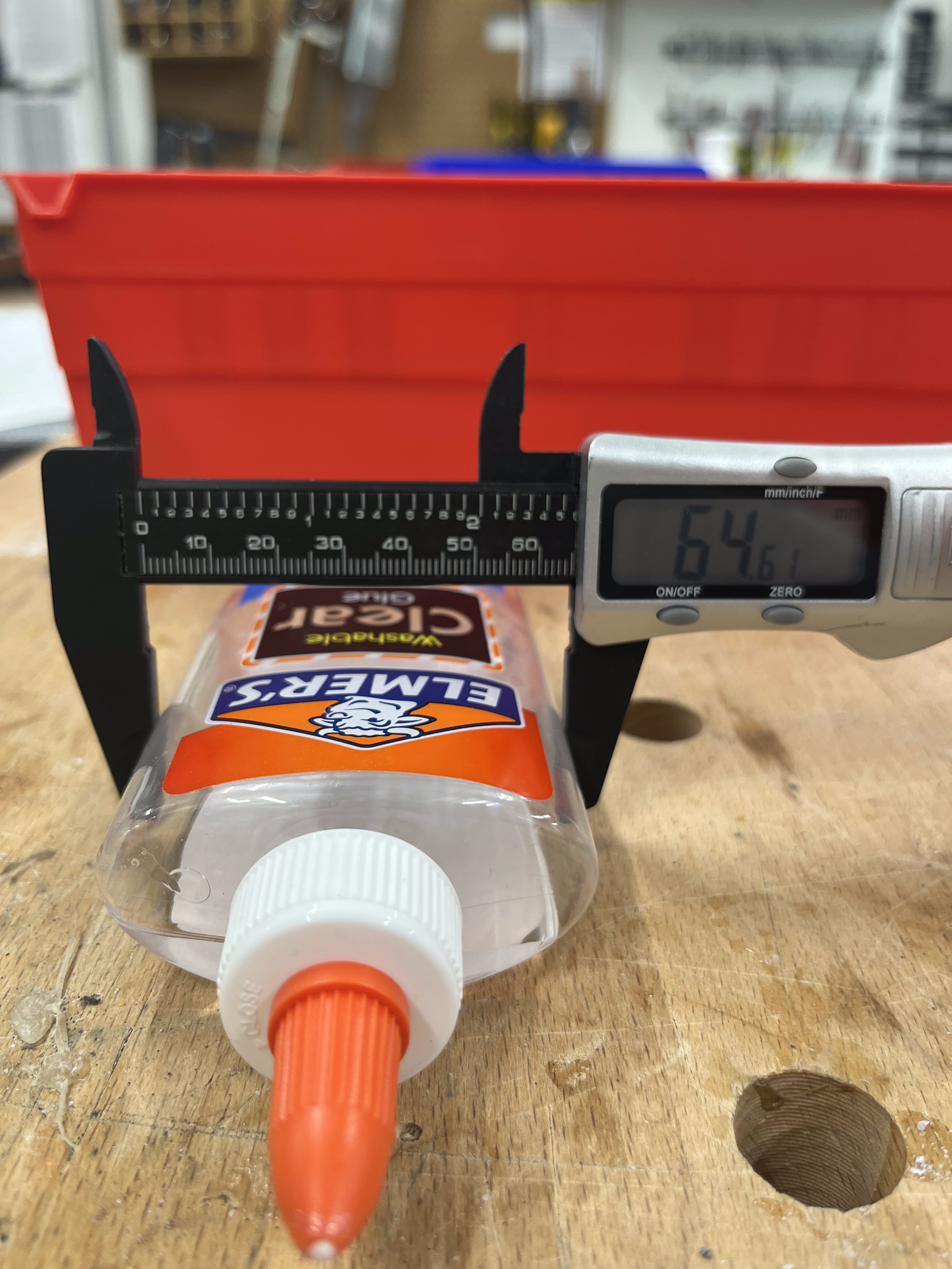
Fig 26. Also Measuring the bottle of glue
Next, I went about constructing a cross-section of the body, extruding it, and adding a fillet to the parameters mentioned above.
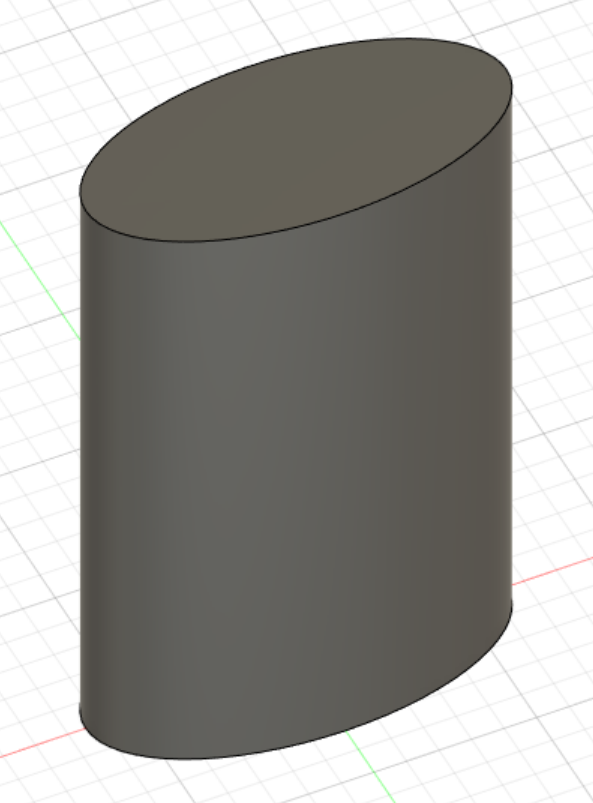
Fig 27. Body extrusion
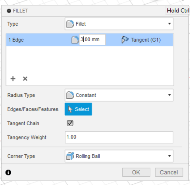
Fig 28. Fillet window and settings
After this, I designed a circle and extruded it to serve as the lower part of my cap, and created a custom spline (which was rotated) to act as the nozzle.
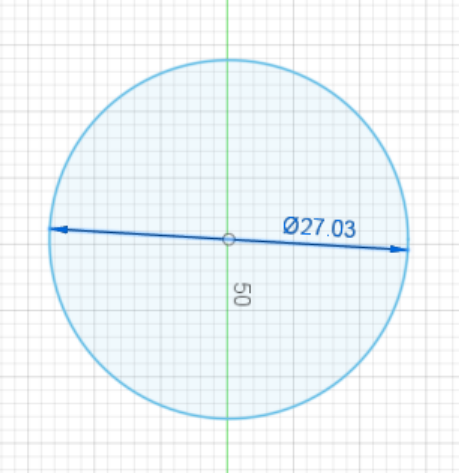
Fig 29. Lower part of cap sketch
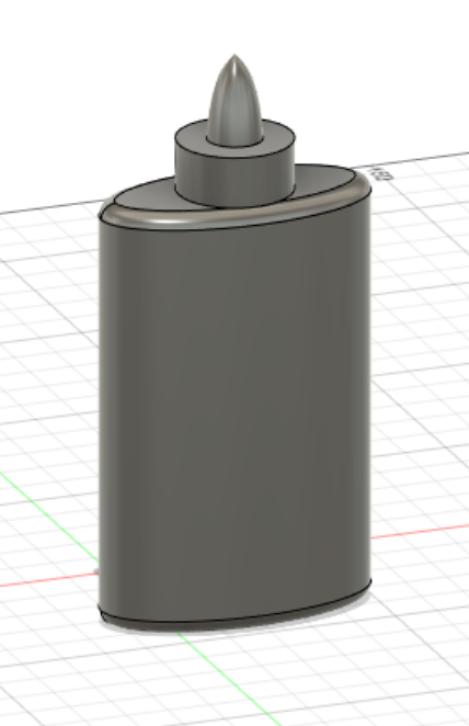
Fig 31. Components assembled
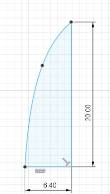
Fig 30. Nozzle sketch
Important: As I mentioned above, this design contains 3 parts (components). I created an assembly to have the act together.
To start, I turned all the bodies into components and I grounded the body that constitutes the bottle. This made it the "base" of the assembly.
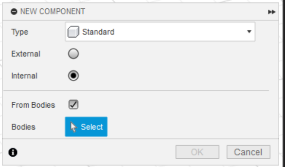
Fig 32. Window used to convert bodies to components
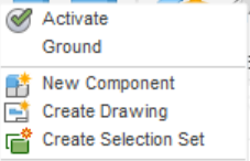
Fig 33. Setting used to ground the base
Next, I created a rotating join between the bottom part of the cap and the body. This allowed it to rotate like a real cap.
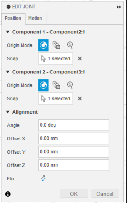
Fig 34. Window used to create joints
Then I created a fixed joint between the nozzle and the bottom part of the cap. This allowed them to rotate together just like in real life.
Finally, I added a bit of coloring and the render was complete!
Fig 35. Final render of glue bottle
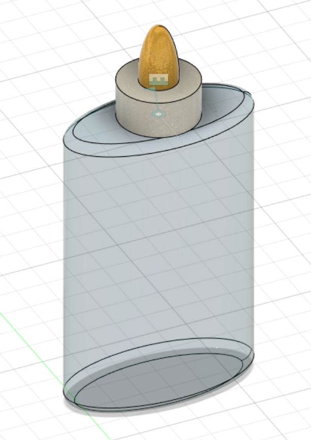
Fig 36. Glue bottle with rotation visible
Concluding Remarks
This project helped me feel very comfortable using Fusion360. I learned a lot of critical design tools such as design patterns, fillets, holes, and assemblies. These tools seem like they will be very useful as I begin to model my final project as well as I begin making designs to 3D print. As I continue to become more familiar with Fusion360, I'd like to learn how to create threads like on a real glue bottle such that rotating the cap would cause it to raise and lower just like a real bottle cap. This similar principle will be useful if I need to model something like gears, where one type of motion can cause other components to exhibit other kinds of motion.
Files Mentioned in this Document
"LEGO" Sketch (.DXF)
Roll of Tape Render (.STL)
Bottle of Glue Render and Assembly* (.F3D)
*This file may not match some of the images above. I made a careless error and forgot to save the file while taking screenshots. It should be similar enough for all practical purposes.